Feasibility study and application of electric energy storage systems embedded in HVDC and STATCOM systems
Electrical power systems are currently experiencing significant changes across all levels of generation, transmission, distribution, and demand. One of the major transitions involves the increasing penetration of renewable energy systems, energy storage assets, and advanced technologies such as Flexible AC Transmission Systems (FACTS) and High Voltage Direct Current (HVDC) links. Concurrently, there is a gradual phase-out of conventional synchronous generation (SG). These changes are transforming the power network into a power-electronics-dominated system. Future electrical transmission grids, characterized by these fundamental changes, require the development of new transmission assets with enhanced capabilities to manage the variability and uncertainty introduced by renewable energy sources.
Members
Convenor (FR)
H. SAAD
Secretary (ES)
E. PRIETO-ARAUJO
F. MOREL (FR), P. JUDGE (UK), D. JOVCIC (UK), K. VERSHININ (FR), A. STEPANOV (CA), V. PATHIRANA (CA), A. EGEA (UK), S. KUBERA (DE) , F. MOHAMMADI (CA), X. WU (CN), H. ERGUN (BE), N. HERATH (CA), F. ERRIGO (FR), F. PAGE (JP), V. RUDAN (FR), L. MENG (SE), M. GOERTZ (DE), P. RAULT (FR)
Introduction
To support the modern power-electronics-dominated network, HVDC links and FACTS devices, particularly STATCOM devices, will play a crucial role. Voltage Source Converter (VSC) based HVDC with Modular Multilevel Converter (MMC) technology has emerged as the preferred solution for upcoming HVDC installations. This preference is due to their improved efficiency, scalability for high voltage levels, compatibility with XLPE cable, reduced footprint, and fast response capability.
The rapid increase in the number and size of electrical Energy Storage (ES) systems is globally driven by their ability to provide the necessary flexibility to integrate intermittent renewable energy sources. As costs decrease and technical improvements (such as energy density and safety) advance, large storage systems are being installed at both distribution and transmission levels in various countries. Integrating ES systems into HVDC or STATCOM devices is expected to introduce or enhance functionalities, providing innovative services to the network, reducing the overall cost and increasing its resilience. These services include improved fault ride-through (FRT) response, black-start capability, dynamic voltage support, (enhanced) grid-forming capacity, fast frequency support, and improved network stability.
This Technical Brochure (TB) B4.84 explores the integration of ES systems in HVDC and STATCOM systems (i.e. ES-HVDC and ES-STATCOM) that are rated in the range of few hundreds of MWs to few GWs and connected at high voltage transmission system levels.
For HVDC systems, different options exist for integrating ES systems depending on the design, requirements, specifications, and cost considerations. Table 1 illustrates the potential locations. It includes integrating ES on the AC side of the converter station, on the DC side of the converter station or into a DC network, or within the converter submodules themselves.
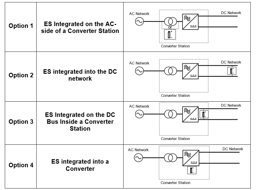
Table 1 - ES Locations in a converter station of HVDC Link
Similarly, for STATCOM applications, ES can be integrated within the modular STATCOM system on the DC bus side or inside the valves as highlighted in Figure 1.

Figure 1 - ES locations in an STATCOM substation
When considering ES-HVDC, it is important to distinguish between the power transferred by the HVDC and the power provided by the ES. The rating of the ES system does not necessarily need to match the HVDC rating and can be smaller depending on the required ancillary services.
The TB presents various MMC converter topologies with embedded ES. To have a common understanding of the circuit topology, the WG has defined new symbols for different circuit structures. As an example, Figure 2 shows the symbol descriptions for MMC with half-Bridge submodules. The battery symbol refers to either supercapacitor or electrochemical battery technologies. The square box refers to ES embedded in the overall converter. Such ES can be partially or fully embedded within the valve. The circle box refers to ES embedded at the valve level. When ES is embedded in the SM, different power electronics interface circuits are feasible that is further elaborated in the TB.
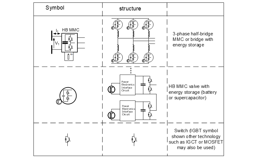
Figure 2 - Symbols definition for MMC half-bridge converter
The document aims to provide key information for power system stakeholders on the ES-HVDC and ES-STATCOM devices. It covers:
- Review of large storage systems
- Analysis and possible MMC topologies for ES integration
- Analysis of different integration options for ES in HVDC/STATCOM systems
- Overview of ancillary services and potential applications
- Benefits for future applications and conventional grid services
- Challenges of integrating ES with HVDC/STATCOM assets
The TB also provides guidelines for developing models to perform dynamic studies with embedded ES in HVDC and STATCOM and highlights several system studies where ES-HVDC can offer significant benefits for system stability.
ELECTRA, is the digital magazine of CIGRE, you can obtain access as part of a CIGRE membership. Find out more about joining options here.
Other Technical Brochures