EMF Consideration for Data Centers Near Transmission Lines: Corridor Width Recommendations
As data centers are increasingly sited near high-voltage transmission lines (HVTLs) for power access and land availability, electromagnetic field (EMF) exposure has become an important design consideration. This article examines EMF impacts on data center infrastructure, including risks to IT systems and control electronics, and underscores the need for EMF analysis in early siting decisions. EMF engineering tools can help model and mitigate EMF exposure, supporting electromagnetic compatibility and reliable operation near transmission corridors.

by Salim Bassam & Soham Ghosh
The Need for Protection from Electric and Magnetic Fields
High-voltage transmission lines are a vital part of the power grid, but they also produce electric and magnetic fields (EMFs) that can pose challenges for nearby infrastructure, particularly data centers. These fields are most intense during peak load conditions, when the lines are carrying their maximum current. For facilities that rely on high-performance computing and uninterrupted data flow, this proximity can introduce risks that are often underestimated during site selection. Sensitive electronic systems, such as servers, storage arrays, and networking hardware, can be affected in several ways:
- Electromagnetic interference (EMI): External EMFs can couple into signal lines, degrading data integrity and potentially causing system instability.
- Induced currents: Magnetic fields can generate unwanted currents in conductive materials, including cabling and circuit traces. This may lead to overheating or component failure.
- Voltage transients: Electric fields can induce brief but damaging voltage spikes, particularly in unshielded or poorly grounded systems.
These risks are not hypothetical. Field studies and operational reports have documented cases where EMF exposure led to unexplained system errors, degraded performance, or premature equipment wear. For this reason, maintaining a safe buffer between data centers and high-voltage lines is not just a precaution. It is a critical design consideration that can significantly impact long-term reliability and operational continuity.
Transmission Corridor Width and Its Impact on Data Centers
The transmission corridor refers to the designated strip of land surrounding a high-voltage power line. This area includes both the mandatory safety clearance and the region influenced by the electric and magnetic fields generated by the line. The width of this corridor is not arbitrary. It directly affects the intensity of EMF exposure in nearby areas, including potential data center sites.
As distance from the transmission line increases, the strength of the electric and magnetic fields decreases. This attenuation is critical for ensuring that EMF levels at the data center boundary remain within safe and operationally acceptable limits. A properly sized corridor helps reduce the risk of electromagnetic interference and supports long-term equipment reliability.
When planning a data center near transmission infrastructure, evaluating the corridor width is essential. It allows designers to make informed decisions about site layout, shielding requirements, and potential mitigation strategies.
Industry Exposure Limits, Industry Guidelines, and Importance of Early Assessment During Conceptual Design
Assessing magnetic field exposure near high-voltage transmission lines involves more than just technical modeling. It requires alignment with a range of standards and guidelines that address both public wellbeing and operational safety. These include regulatory exposure limits, occupational safety recommendations, and utility-specific best practices.
The goals of these frameworks are:
- To protect human wellbeing from potential effects of long-term EMF exposure.
- To ensure the operational reliability in sensitive environments such as data centers, where electromagnetic interference (EMI) may compromise safety-critical systems or storage devices (e.g., HDDs, SSDs, servers).
For example, the Florida Department of Environmental Protection outlines EMF exposure standards in Rule 62-814.450, see Table 1. This regulation provides a reference point for evaluating acceptable field levels during the planning and permitting phases.
kV rating | Property boundary of new substation | Edge of transmission line Right-of-Way |
|---|---|---|
<=230 kV | 2.00 kV/m and 150 milliGauss | 2.00 kV/m and 150 milliGauss |
<=500 kV and > 230 kV | 2.00 kV/m and 200 milliGauss | 2.00 kV/m and 200 milliGauss |
>500 kV | 5.50 kV/m and 250 milliGauss | 5.50 V/m and 250 milliGauss |
Another example standard for ensuring operational reliability in sensitive environments such as data centers comes from TIA-942-C. Annex F, Table 7 [2], see Table 2.
| Electromagnetic fields | Magnetic flux density |
|---|---|
| Maximum magnetic field recommended unless more restricted recommendations from μEDC equipment manufacturer | As per IEC-61000-4-8 (below 37.5 mG or 3.75 μT) |
Incorporating EMF assessments early in the conceptual design phase is crucial. It enables project teams to identify potential risks, coordinate with utility providers, and implement design strategies that ensure compliance and performance. Early planning also helps avoid costly retrofits or operational disruptions later in the facility’s lifecycle.
Tools like CDEGS-EnvroPlus, EPRI, ANSYS maxwell help model EMF environments and guide safe, efficient data center planning. The CDEGS SESEnviroPlus software suite in particular is a robust tool specifically designed for analyzing electromagnetic fields (EMF) in areas affected by high-voltage infrastructure. SESEnviroPlus excels in considering uneven charge distribution on conductor surfaces, enhancing the precision of electric field calculations in proximity to the conductors. This software offers a reliable and precise modeling platform by incorporating detailed input factors like conductor structure, current strength and phase, soil characteristics, and spatial arrangement to replicate the electromagnetic conditions.
Minimum Corridor Widths and Effect of Circuit Layout
For optimal protection of data centers from electric and magnetic fields, it is recommended that minimum transmission corridor widths account for multiple factors, including transmission voltage level, current during peak load, and equipment sensitivity. While voltage level is an important consideration, a factor that is often overlooked is the circuit configuration of the transmission line. The physical arrangement of conductors significantly influences the distribution and intensity of electric and magnetic fields at ground level.
To illustrate this, three common transmission configurations are showcased in Figure 1, each requiring different minimum corridor widths to achieve safe EMF levels for data center electronics:
- Single Circuit Vertical Configuration: This setup typically concentrates the magnetic field closer to the centerline, but the field can extend further laterally due to the vertical stacking of phases. Wider corridors may be necessary to ensure safe field levels at data center boundaries.
- Double Circuit Vertical Configuration: With two vertically stacked circuits, this configuration increases the overall current and EMF intensity. It generally requires a greater corridor width compared to a single circuit to reduce field strength to acceptable levels. However, in the vicinity of a data center, the phase conductors for the two circuits can be transposed to partially cancel each other allowing the resulting electric and magnetic fields to comparable values as that of a single circuit.
- Single Circuit Horizontal Configuration: The horizontal arrangement generates a much wider electromagnetic field, often resulting in a broader corridor width for comparable voltage levels.
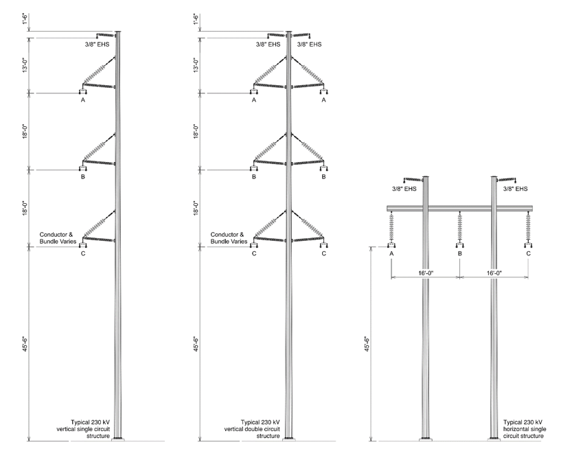
Figure 1 - Showcasing different circuit configuration at same voltage level. The choice of the circuit configuration has an impact on the electrical and magnetic field
Figure 2 shows the electrical and magnetic fields for each of the three circuit types, further illustrating the fact that double circuit vertical conductor arrangement with transposed phases can carry more electrical power without a proportionate increase in the electrical and magnetic fields, compared to its single circuit vertical conductor counterpart. Figure 2 also shows a visual depiction of the magnetic field threshold and the separation distance needed for data center placement.
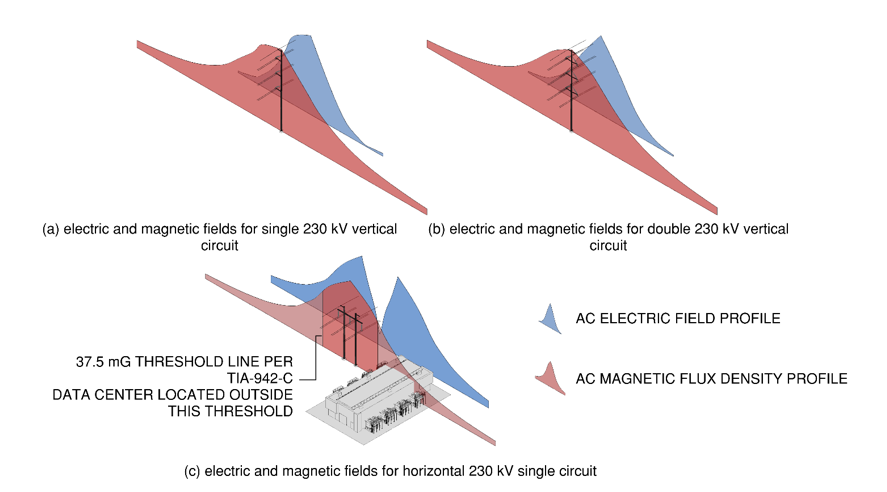
Figure 2 - Showcasing the electric field and magnetic flux density profiles for different circuit arrangements. Observe that the horizontal circuit layout has a much wider electric field layout which might not make it an optimal circuit configuration for cases where there is a data center at close proximity
Mitigation strategies if proximity to transmission lines cannot be avoided
When a data center must be sited near high-voltage transmission lines, several design and operational measures can help reduce the impact of electric and magnetic fields on sensitive equipment:
- Increasing Distance from the Source:
Electromagnetic field strength decreases significantly with distance from the conductors. This can be achieved by:- Increasing structure height: Raising the height of transmission towers elevates the conductors, increasing the vertical separation from ground level and reducing field intensity in accessible areas.
- Centering conductors within the right-of-way: Positioning the conductors closer to the centerline of the transmission corridor, rather than near the edge, helps minimize magnetic field levels at adjacent property lines. These adjustments are particularly effective in reducing exposure at the boundaries of the corridor, where buildings or personnel may be located.
- Reducing Conductor (Phase) Spacing:
The magnetic field produced by a three-phase system is influenced by the spacing between conductors. Reducing the distance (within the bounds of safe electrical clearance) between phases enhances field cancellation and lowers the net magnetic field at ground level.
- Optimizing Circuit Phasing:
When multiple circuits are installed on the same structure, the total magnetic field is the vector sum of the fields from each conductor. By carefully selecting the phasing of each circuit, it is possible to achieve partial cancellation of magnetic fields. This technique, known as optimal phasing, is particularly effective in double-circuit towers and can significantly reduce magnetic field levels at ground level.
Conclusion
The proximity of data centers to high-voltage transmission lines poses significant risks to the operation of sensitive electronic equipment. The minimum recommended transmission corridor width plays a crucial role in reducing the strength of the electric and magnetic fields that could interfere with data center electronics. By following established guidelines and understanding the factors that influence EMF exposure, data center operators can mitigate these risks and ensure that their equipment remains reliable, safe, and compliant with regulatory standards.
As the digital economy continues to expand, understanding and managing the relationship between data centers and their surrounding power infrastructure will be key to maintaining seamless and secure operations in an increasingly connected world.
References
- Florida Department of Environmental Protection, "Rule 62-814.450: Electrical and Magnetic Field Standards," 2021.
- Telecom Industry Association, "TIA-942-C: Telecommunication Infrastructure Standard for Data Center," 2020.
Want to go further? Discover related Technical Brochures on eCIGRE
► TB 806: Responsible management of electric and magnetic fields (EMF)
► TB 748 : Environmental issues of high voltage transmission lines in urban and rural areas
Thumbnail credit: Ai generated image by Nika on Lummi
Suggested content