Assessment of conducted disturbances above 2kHz in MV and LV power systems
This Technical Brochure provides an assessment of conducted disturbances above 2kHz in MV and LV power systems. The aims of the brochure are: to raise awareness of the issues involved, provide a technical description of the phenomena, identify existing recommendations and guides and identify gaps for future work. It includes information on electric power definitions, measurement techniques, modelling and aggregation. The method for measuring and calculating conductor impedances are fully described and an example study of the aggregation and propagation of the conducted emissions above 2kHz are provided as a demonstration.
Members
Convenor
(UK)
D. THOMAS
Secretary
(IE)
K. ATKINSON
A. MOHOS (HU), I. ANGULO (ES), J. LADÁNYI (HU),
R. HUBBARD (SA), F. SOLLERKVIST (SE), H. SIEW (GB), D. VUJATOVIC (GB), G. VARJÚ (HU)
Corresponding Members: M. BOLLEN (SE), I. FERNANDEZ (ES), A. ROCH (NL), R. SERRA (NL), J. SKANSENS (SE), E. SMULDERS (NL),
R. SMOLENSKI (PL), P. LEZYNSKI (PL), P. IVRY (GB), M. YESHALEM (GB)
The electricity supply industry has been transformed in operation and efficiency through the increased use of power electronic converters, smart meters and communication links. In particular the use of Power Line Communications (PLC) has become an important part of smart meters and smart grid solutions. Power electronic converters and PLC, however, superimpose disturbing voltages through conducted emissions at frequencies different from the mains frequency thus distorting its sinusoidal waveform and threatening the interoperability of all connected mains equipment [1]. The frequency range 2-150 kHz has been mostly unregulated in the past, but this is the primary frequency range where problems are occurring due to conducted emissions. A detailed description of the sources and effects can be found in [2]. There is, therefore, an increased interest in the nature of mains disturbances in this frequency range. The focus of this Technical Brochure (TB) is then the higher frequency conducted emissions over the range 2-150 kHz and issues related to equipment connected to MV and LV power systems.
The frequency range 2-150 kHz is often called supraharmonics. The measurement and analysis must fully allow for the time / frequency characteristics of the supraharmonics. These supraharmonics have time variations within one mains cycle and have broadband components as shown in Figure 1. At present there are no agreed standards for the measurement of the voltage and current emissions in the frequency range 2-150 kHz. Care needs to be taken over the chosen receiver bandwidth and the time duration over which measurements are taken. It has been found that popular methods for assessing supraharmonic emissions can lead to overlooking important features and may not provide a representative measure of possible interference [3]. This could lead to inappropriate mitigation procedures.
In order to assess the impact of supraharmonics, their propagation and aggregation also needs to be fully understood. Although supraharmonics have properties that are synchronous with the mains frequency (i.e. zero crossing impulses), they are mainly generated by pulse width modulation clocked by an unsynchronised oscillator. Supraharmonics, therefore, differ from the lower frequency harmonics in that they have a strong time variation and the sources tend to be uncorrelated. Supraharmonics propagate mainly along conductor paths. The power system impedance has a very strong frequency variation in the range 2-150 kHz due to the skin effect [4] and has a very strong time variation due to the switching of nonlinear loads [5]. The estimation of the propagation and aggregation of supraharmonics in a power system is, therefore, quite complex and not yet fully understood.
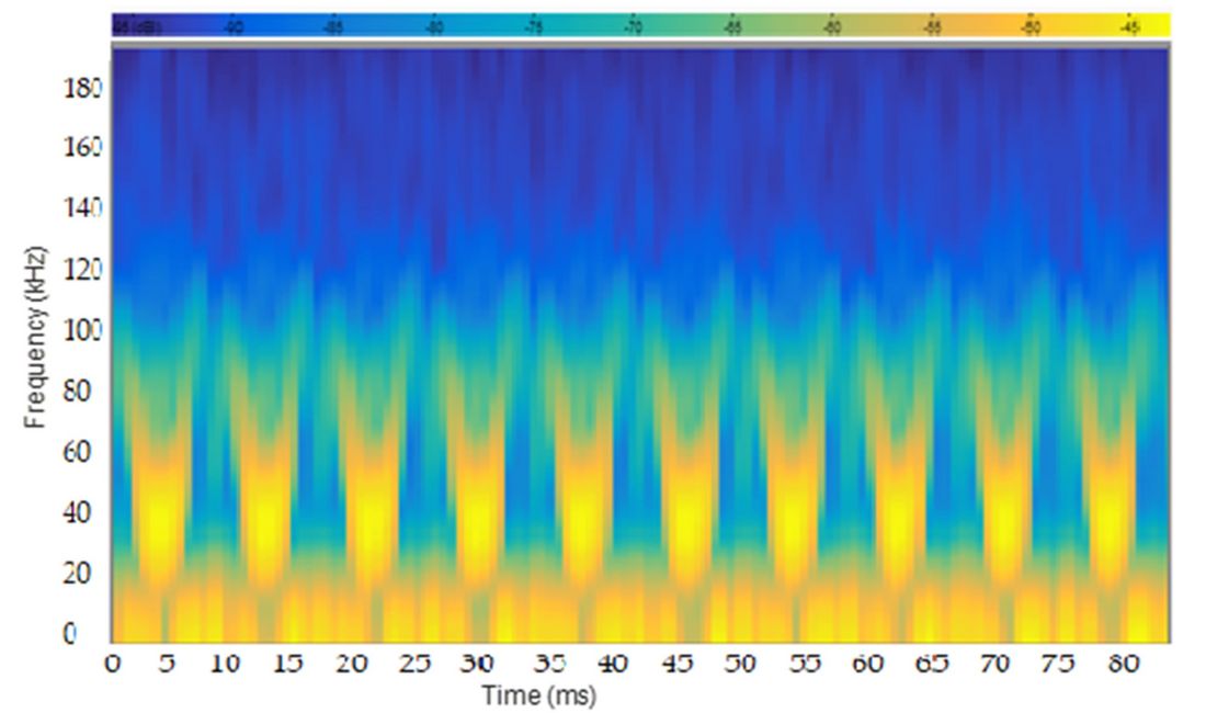
Figure 1 - STFT spectrogram for the current from a single 36 W Fluorescent light bulb
Only relatively recently have compatibility standards for the frequency range 2-150 kHz been published [6]. For this reason, the available emission limits (intentional and unintentional) and immunity levels [7] are not in full agreement. More work is required to harmonize standards for supraharmonics but this can only be achieved through a better technical understanding of the phenomena.
Scope of work
The aims of the Technical Brochure are to:
- Raise awareness of the issues involved
- Provide a technical description of the phenomena
- Identify existing recommendations and guides
- Identify gaps and future work
The Technical Brochure is not intended to prescribe limits; however reference has been made where appropriate to on-going work in this area which in the future is expected to result in standardisation of limits in this frequency range. The Technical Brochure includes information on electric power definitions, measurement techniques, modelling and aggregation.
EMI in the frequency range 2-150 kHz can be broadband, narrowband or recurrent and due to the conducted emissions from power converters and unintentional components from mains communications systems. These sources are briefly described in the Technical Brochure. Intentional narrowband signals are also derived from mains communications systems. The Technical Brochure describes how the different components can be evaluated through the use of Short Time Fourier Transforms (STFT) with appropriate filtering.
The methods for measuring and calculating the conductor impedances are fully described in the Technical Brochure. An example study of the propagation and aggregation of the supraharmonics within a solar park is provided as a demonstration. It is found that:
- It seems that inverters influence each other, thus supraharmonic currents are more likely to flow between them than into the grid;
- The alteration of the harmonic production does not significantly change with the injected current at the switching frequency;
- The aggregation of different harmonics seems to be a stochastic process. Probably it cannot be described with an exact, useable mathematical form:
- At 16 kHz the resultant current of 10 PV units is nearly the same (in some cases even lower) as the currents of the individual PV panels;
- At 19 kHz the resultant current of 10 PV units is nearly 5-10 times higher than the individual currents of the PVs;
- The change in power production of a PV unit does not significantly change the injected disturbing current at switching frequency;
- Conclusions relating to attenuation cannot be drawn from these measurements because we could not measure the same inverter’s current in two places at the same time (e.g. at the inverter and at the distribution board);
- The measured current emission values in the 2 kHz to 30 kHz frequency range are far below the immunity test levels set in standard IEC 61000-4-19 [8].
These results are consistent with the findings of other researchers [9]. The Technical Brochure also provides a brief description and discussion of the relevant standards.
- [1] [a] IEC SC 205A Study Report on Electromagnetic Interference between Electrical Equipment/Systems in the Frequency Range below 150 kHz CLC/FprTR50669:2017. [b] F. Leferink, C. Keyer and A. Mclentjev “Static Energy Meter Errors Caused by Conducted Electromagnetic Interference” IEEE EMCS Magazine 3 March 2017.
- [2] IEC SC 205A Study Report on Electromagnetic Interference between Electrical Equipment/Systems in the Frequency Range below 150 kHz CLC/FprTR50669:2017.
- [3] [a] M. Klatt, J. Meyer, P. Schegner, "Comparison of measurement methods for the frequency range of 2 kHz to 150 kHz," in Harmonics and Quality of Power (ICHQP), 2014 IEEE 16th International Conference on, pp. 818-822, 25-28 May 2014. [b] P. Lezynski, R. Smolenski, H. Loschi, D. Thomas, N. Moonen “A Novel method for EMI evaluation in random modulated power electronic converters” Accepted for publication in “Measurement”, Elsevier 2019.
- [4] A. Mohos, J. Ladanyi, D. Divenyi “Methods to ascertain the resistance of stranded conductors in the frequency range 40 Hz-150 kHz.” Electric Power Systems Research, Vol 174, Elsevier 2019, doi.org/10.1016/j.epsr.2019.105862.
- [5] D. Chakravorty, J. Meyer, P. Schegner, S. Yanchenko and M. Schocke “Impact of modern electronic equipment on the assessment of network harmonic impedance” IEEE Trans. Smart grid, Vol. 8 (1) Jan. 2017.
- [6] IEC Electromagnetic compatibility (EMC) – part 2-2 IEC Std. 61000 2-2 Ed2 A1/CD: Environment — Compatibility levels for low-frequency conducted disturbances and signalling in public low-voltage power supply systems, IEC 61000-2-2:2018, ed2am1am2.
- [7] [a] IEC Technical Specification “Power electronics systems and equipment — Operation conditions and characteristics of active infeed converter (AIC) applications including design recommendations for their emission values below 150 kHz” IEC/TS 62578:2015: ISBN 978 0 580 75477 7. [b] EN Std. 61000 Electromagnetic compatibility (EMC) –Part 4-19: Testing and measurement techniques — Test for immunity to conducted, differential mode disturbances and signalling in the frequency range 2 kHz to 150 kHz at a.c. power ports, EN 61000-4-19:2014.
- [8] EN Std. 61000 Electromagnetic compatibility (EMC) –Part 4-19: Testing and measurement techniques — Test for immunity to conducted, differential mode disturbances and signalling in the frequency range 2 kHz to 150 kHz at a.c. power ports, EN 61000-4-19:2014.
- [9] CIGRE JWG C4/C6.29, TB 672 “Power Quality aspects of solar power”, December 2016 ISBN: 978-2-85873-375-0.

Other Technical Brochures