Implications for harmonics and filtering of the installation of HVDC converter stations in close proximity
This Technical Brochure examines the full extent of possible technical concerns in the area of harmonics and filtering of the installation of HVDC converter stations in close proximity. It provides guidance on the pre-specification studies to screen the possibility of harmonic interactions and to determine specific system data and technical requirements, such as network harmonic impedance, reactive power controller philosophy and harmonic limits. It will also provide a basis of knowledge of the aspects to be considered in performance and rating studies and the possible implications for the design of the filtering equipment. The possible approaches for co-ordination of filter designs is discussed in the Brochure, taking into account not only technical aspects, but also economic, contractual and regulatory points of view, particularly in an environment with multiple vendors and owners.
Members
Convenor
(BR)
F. CATTAN JUSAN
N. SHORE (GB), S. MUKOO (DE), T.GEORG MAGG (ZA), I. FERNANDO (CA), N. CUNNIFFE (IE), M. CORREIA LIMA (BR), M. PIRES DE CARLI (BR), S. SANKAR (US), A. GANGADHARAN (IN)
Introduction
The connection of HVDC converter stations in close electrical proximity is a major concern in large power systems and leads to several potential effects that need to be carefully addressed by the engineers responsible for the planning, specification, design and operation of HVDC systems. Many technical aspects have been covered in previous CIGRÉ Working Groups, but a number of topics needed further discussion and more practical guidance, particularly in the field of harmonics and filtering.
CIGRE Working Group B4.66 was formed to analyse the full extent of possible technical concerns, provide background information and make suitable recommendations. This Technical Brochure presents the outcome of these investigations.
The basic problem can be stated as follows: if two converter stations are electrically far from each other, the design of the AC filters at one station may be made with little regard to the harmonic characteristics of the other station. If however the electrical distance between converter stations is relatively short(in the worst case at the same busbar) or there is a resonance condition in the network connecting the two stations, then the filter performance of one station will possibly be affected by the impedance and harmonic generation of the other station. In addition, the rating of the filters of one station must take into account the contribution from harmonic currents generated at the other station, which under severe resonance conditions may even be higher than those generated locally.
Consequently, an independent design of the AC filters of proximate HVDC stations will generally lead to non-optimized or even incompatible filter solutions. Lack of clarity in the design requirements and insufficient information in the Technical Specification on how to take into account the possible harmonic interactions may result in lengthy discussions during contract stage, re-design and possibly project delay. The cost-impact of these issues can be very high. Co-ordination is therefore essential to achieve compatibility of filter designs.
A further complexity is introduced when the proximate converter stations are developed by different HVDC manufacturers and/or owned by different Customers, a scenario that is becoming increasingly common in open transmission markets worldwide. The evaluation of the joint operation requires the exchange of main circuit data, converter harmonic generation, filter characteristics and design assumptions between the owners/operators or more specifically between the HVDC manufacturers concerned with the detailed design of the two HVDC stations. A strong collaboration effort and co-operation may be required to verify filter compatibility and allow for optimization. Besides, contractual and legal issues play a major role in this multi-vendor/multi-owner environment and can affect the resulting global filter solution. This is discussed in further details in the Brochure.
Scope
The Brochure is mainly addressed to point-to-point HVDC projects using line-commutated converter (LCC) technology. However, many topics are equally relevant for schemes using voltage source converters (VSC) as well as other non-HVDC applications in close proximity to a converter station, such as FACTS devices, wind power plants or any other large harmonic producer.
Objectives
In preparing this Brochure, WG B4.66 has attempted to:
- Assess the issues which have risen in the specification, project execution and field operation of AC filters of recent HVDC projects which fall into this category;
- Recommend suitable modelling techniques and calculation methods, so that the AC harmonic interactions are properly evaluated and taken into account by the filter designers;
- Examine how particular aspects of harmonic interactions between proximate converter stations can impact the performance and rating of the harmonic filters of both stations;
- Provide guidelines for the co-ordination of filter designs, taking into account economic implications and regulatory aspects;
- Provide recommendations for the implementation and co-ordination of the reactive power control functions of the HVDC stations;
- Review the recommendations of IEC 61000-3-6 for the specification of harmonic limits;
- Review existing methodologies for the assessment of individual harmonic emissions at site;
- Examine how the recommendations resulting from this work can be incorporated in future specifications of HVDC projects.
Representation of AC network harmonic impedance
If the converter stations are connected to the same busbar, the network impedance can be represented using the classical approach of envelope diagrams, as in a single-infeed system. However, if the converter stations are located at separate busbars, this approach is no longer appropriate and the harmonic calculations require the knowledge of the harmonic coupling impedance between converter stations. If the AC system is a small and well-defined network, it may be preferable to model the transmission lines, cables, generators, transformers, etc. explicitly. If however the network is a large meshed grid with thousands of buses and branches, this approach is not feasible and the entire network may be reduced to retain only the busbars associated with the studied converter stations. For a two-infeed system, equivalent T-section or π-section networks (as illustrated in Figure 1) may be derived from simple frequency scans of the full network model using a standard commercial program. The calculation process is described in the Brochure.
These calculations should be preferably carried out by the Customer or by the Network Owner (rather than by the prospective Contractors) prior to issuing the Technical Specification. The resulting equivalent network parameters for each harmonic order and network condition (including future evolution of the network) shall then be included in the Technical Specification. This approach avoids different Bidders making their own assessment with the provided raw network data (usually in the form of load flow data), unnecessarily duplicating effort and possibly obtaining different results.
Harmonic performance evaluation
Suitable circuit models and study methods shall be used by the filter designers. The circuit models for studying the potential harmonic interactions are different depending if the converter stations are located at the same or at an electrically close busbar.
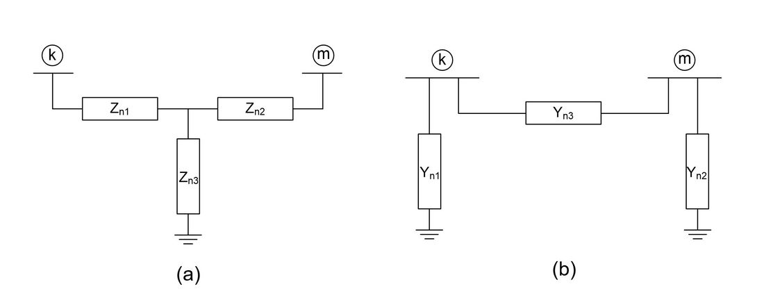
Figure 1 - Equivalent network for harmonic interactions studies: (a) T-section; (b) π-section
HVDC schemes connected at the same AC busbar
When the converter stations are connected to the same busbar, the overall performance evaluation process is similar to the case of a single-infeed system, but the AC filters from both installations should be represented in the circuit model, as shown in Figure 2.
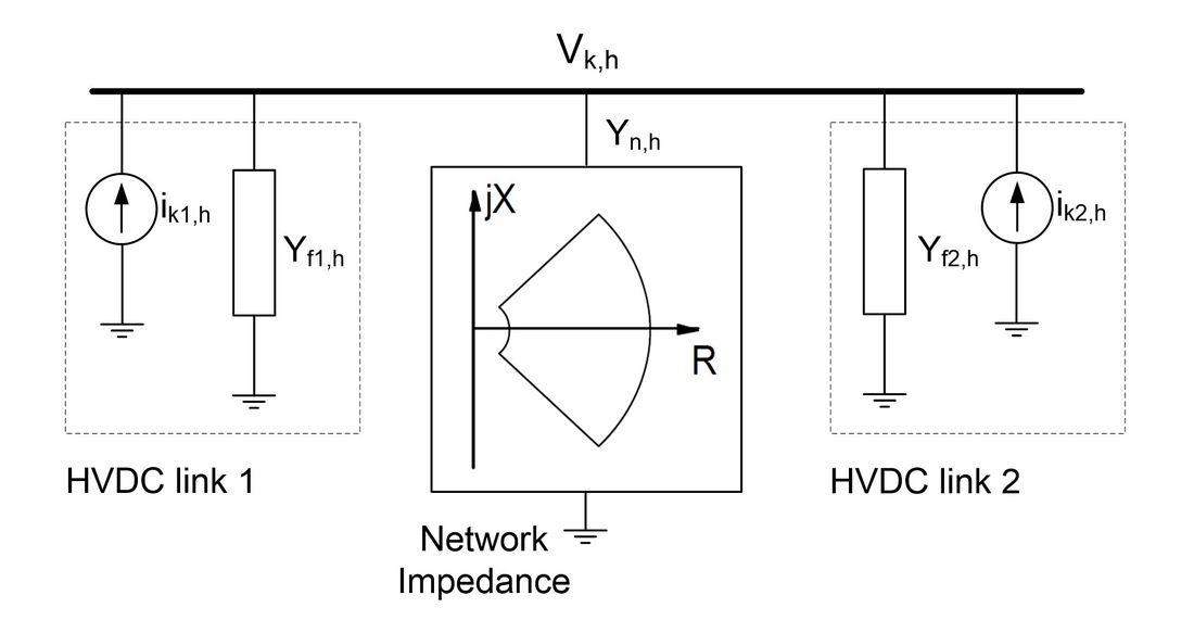
Figure 2 - Circuit model for two HVDC converters connected at the same busbar
Simultaneous detuning of the filters of the two stations is evaluated under specified conditions to find the overall worst-case resonance between filters and AC network. To cover the entire power range on both HVDC links (from blocked state to nominal power), different consistent sets of filter sub-banks on both converter stations need to be considered in the calculations.
HVDC schemes connected at separate AC busbars
When the HVDC converters are connected at different busbars, the harmonic interaction between two schemes can only be studied by modelling the network elements explicitly or by the use of equivalents, as explained in the previous section. The complete circuit model is illustrated in Figure 3, where a π-section equivalent network has been used.
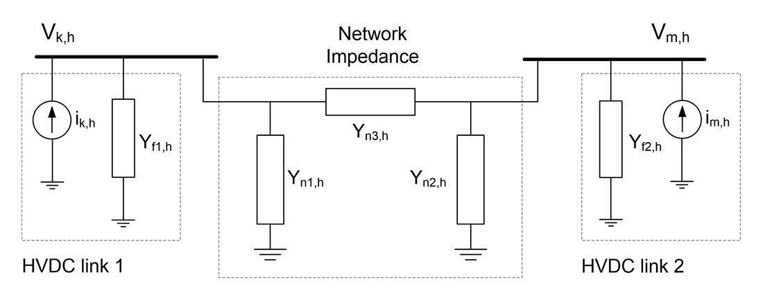
Figure 3 - Circuit model for two HVDC converters connected at separate busbars
Although technically possible, a fully detailed joint performance study of a multi-infeed system representing the coupling impedance between converter stations under all possible operating configurations, load levels and detuning conditions would be a very complex and time-consuming task in practice. A more reasonable approach is to perform the study in two steps. First, neglect the harmonic generation of the other HVDC link and include its filters in the network impedance seen by the studied converter station (using nominal parameters and a few detuning conditions). This would allow the designer to use the conventional and systematic method of envelope diagrams. This first assessment must be complemented in a second step by a detailed analysis using the circuit model of Figure 3 for specific system configurations agreed between Customer and Contractor, taking into account the simultaneous detuning of the filters of both stations, filter outages and the overall effect of both current injections.
Filter rating evaluation
In a multi-infeed HVDC configuration, the filter components of a particular converter station will be stressed not only by the harmonics generated locally, but also by the harmonics coming from other proximate HVDC links (or any other large harmonic producer) through the AC network. If these additional stresses are not properly considered in the design, the filters may be inadequately rated, which could result in limitations on HVDC operation and power transfer, possible damage to filter equipment or cascaded tripping of overloaded filters resulting in complete shutdown.
A detailed steady-state rating evaluation may be performed with the same basic circuit models used for performance design. Some assumptions may differ from those used for performance calculations, such as: range of power, network contingencies, outage of filter sub-banks, range of system voltage and frequency, etc. Ideally, non-feasible operating conditions involving the multiple HVDC links should not be considered. A clear definition of the possible multi-infeed operating conditions and network configurations should be provided by the Customer. Similarly, transient rating studies must consider not only internal faults and switching operations on the converter station under design, but also switching events on the other station, such as converter transformer and filter energisation. Therefore, it is important that an accurate model of the main circuit components and switching control equipment of the other HVDC link is considered in the simulations.
Combining harmonics generated by different converter stations
The vector relationships between the individual harmonics generated by the two converter stations will depend on the operating conditions, load level and on the relative phase angle of the fundamental frequency busbar voltages where the converters are located, which may be quite different from one operating state to another. If detailed information is provided by the Customer for each case as part of the consistent sets of network operating conditions, then actual vector sum may be used by the Contractor, leading to more realistic results. When this data is not available (which is often the case), the Customer should clearly state in the Technical Specification how the individual components should be added. The most conservative approach is to assume that the harmonics are in phase and can be added arithmetically. For certain harmonics this may be suitable, if the HVDC converters are connected at the same busbar and the source of the distortion is related (e.g. 3rd harmonic due to system voltage negative sequence). In other cases this is unduly pessimistic, such as when the converters are located at different busbars or when the sources of distortion are not related, such as in the case of non-characteristic harmonics originated from firing angle asymmetries (jitter).
Pre-existing harmonics
When the level of interaction between two HVDC converter stations is negligible, the harmonic generation of the remote station can be regarded simply as part of the pre-existing harmonics. However, if there is significant coupling, it is strongly recommended that the effect of the proximate HVDC station and its filters is evaluated by explicitly including them in the circuit model used for harmonic analysis, as described in the previous sections. This is justified due to the completely different natures of pre-existing harmonics and HVDC converter-generated harmonics and to possible resonance conditions which would not be readily identified by the model of pre-existing harmonics.
If the converter stations are connected at the same busbar, the pre-existing harmonics can be represented by a Thevenin equivalent and the worst-case resonance between network impedance and filter impedance of the two stations can be found by a systematic search (considering any feasible combination of filter sub-banks and simultaneous detuning of filters), as in the single-infeed case. When the converter stations are located at different busbars, the effect of pre-existing distortion can no longer be modelled by a single Thevenin equivalent. The Brochure discusses possible approaches on how to consider its effects on performance and rating studies.
Filter design co-ordination
Two different HVDC manufacturers may propose quite different AC filter arrangements for identical or near-identical HVDC converter installations, depending on the technical assumptions and preferences for filter design. Both filter solutions may comply with the same technical requirements in stand-alone operation, but the joint operation may still not be satisfactory. The Brochure discusses the implications of independent filter designs and the possible approaches for co-ordination, taking into account not only technical aspects, but also economic, contractual and regulatory points of view, particularly in an environment with multiple vendors and owners.
Potential problems with independent filter designs
A number of potential problems can occur during joint operation if the AC filters of two proximate HVDC converter stations are specified and designed independently from each other:
- Unequal sharing of harmonic load between filters
- Unpredictable resonance between filters
- Low order resonance between the combined filters and the network
- Overload of filters due to amplification of remotely generated harmonics in the presence of resonances in the network
- Harmonic instability
- Excess of reactive power at low power levels
- Overload of the filters of one station due to transformer energisation on the other station
The Brochure discusses each of these problems in details and illustrates some of them through simple worked examples in a set of appendices.
Situations where filter design co-ordination can be important
The evaluation of the harmonic interactions and co-ordination of filter designs between independent converter stations may be required for several practical situations, such as:
- Installation of a new HVDC scheme electrically close to an existing converter station → the usual approach is to design the AC filters of the new scheme so the existing filters are not impacted. If however the existing filters were designed a long time ago, with significantly different design assumptions on network characteristics, pre-existing harmonics, detuning factors, etc., an overly costly and complex filter scheme may be required and the overall project time schedule may be compromised due to much higher engineering time and effort. In this case, it might be advisable to up-rate or replace (partially or totally) the existing filters. The simplifications and cost savings achieved for the new filters may compensate for the extra costs needed to modify the existing filters. A detailed technical and economic analysis should be performed in the early stage of the project to indicate the optimum approach to follow.
- Staged installation of a planned HVDC project → a transmission block of some thousands of MW is normally split in smaller blocks (e.g. two or three bipoles) staged over several years. Such staging of the transmission system is typically done in order to match transmission capacity to the build-up of generation capability or load growth. The goal is to define suitable guidelines and requirements to fairly share the responsibility among schemes’ designers in the process of co-ordination and overall optimization of filter designs. This would also avoid penalising the latter scheme due to incremental design approach.
- Replacement, refurbishment or upgrade of converter stations → in order to extend the life cycle or enhance power transmission capacity of an HVDC scheme, sometimes selective replacement or upgrade of aging components and sub-systems is decided by the Customer. The scope may include the replacement of the AC filters of the converter station; in this case, if there is another HVDC scheme connected at the same or proximate AC busbar whose filters will not be included in the scope of the refurbishment, the harmonic interactions between these filters and the new filters (or modified filters) must be carefully investigated. Sometimes an exact one-to-one replacement is possible, but in certain instances a full re-design may be necessary.
- A new HVDC scheme with a large SVC or STATCOM nearby → in many applications, dynamic reactive power compensation devices are installed close to a converter station in order to improve voltage control during system disturbances. The mutual influence of harmonic generation and filtering between both HVDC and SVC/STATCOM must be carefully considered.
- A new multi-terminal HVDC system with proximate AC connection points → the terminal stations of a point-to-point HVDC scheme are normally electrically far from each other. However, in a multi-terminal HVDC system, two or more terminal connections can be at proximate locations, so harmonic interactions via AC network may become significant and need to be considered in AC filter design.
Design co-operation in an environment with multiple stakeholders
Various issues concerned with proximate converter stations call for co-operation and exchange of information between the Owners/Operators or more specifically between the HVDC manufacturers concerned with the detailed design of the two HVDC stations. The information required by the designers of each station is essentially that which is necessary to model the harmonic emissions from the converter and the harmonic impedance of the HVDC station under all conditions. Information required to evaluate switching events (e.g. transformer energisation) which might lead to additional stresses in the existing low order harmonic filters is also important.
The desired exchange of information may face several obstacles. Firstly, it may conflict with the natural secrecy maintained between competitors, who may not wish their design methods to be transparent to others or for their design to be exposed to alternative calculation by others. Secondly, it may risk being in contravention of anti-trust regulation which inhibits collusion between market competitors. Thirdly, it will require the approval of the owner of the HVDC stations (or owners if these are different entities). This process appears not to be difficult, as it is in the interests of all parties to ensure a successful design. But given the possible issues involved and the rules and regulations in different organizations, it may require project managers to seek advice and rulings from their legal departments before approving information exchange.
It may therefore be necessary to draw up a special contractual agreement among the parties involved, with legal approval, defining exactly the permissible extent of information exchange and the channels through which such information is to be communicated, as well as limiting the use and distribution of information obtained in this manner. Rules governing contact between individual engineers must also be clearly defined.
It is clear therefore that in practical terms, the above procedures may take a significant amount of time, and this should be foreseen and planned for in the project design schedule. The engineers involved should take particular care to define exactly what information is required to ensure adequate co-ordination of design, as discussed throughout this Brochure. Lists of required data should be prepared, possibly with the justification for requesting such items. Lists should be comprehensive, as it may prove difficult to add data to the agreement at a later stage.
Regulatory framework implications
In power systems under liberalized electricity markets, each transmission asset is normally treated as a single independent entity from the legal and contractual point of view. Therefore, each proximate converter station is independently regulated and individually subjected to penalties for non-compliance with harmonic regulations, even if other converter stations are connected at the same AC busbar. So, a global optimum filter solution may be not allowed.
This was the case of Rio Madeira HVDC project, in Brazil, where the same manufacturer was responsible for designing and constructing the AC filters of a back-to-back and a bipole on the same site and connected at the same 500 kV busbar. The two projects were developed simultaneously. But because the two schemes belonged to different transmission concessionaires, it was necessary for contractual and regulatory reasons to provide separate filter sets, each with its own redundancy, rather than to design the most efficient common filtering solution that covers both projects.
In some parts of the world, proximate HVDC converter stations may be electrically close but physically located in separate countries where different harmonic regulations and definitions of acceptable harmonic limits may apply. This factor may further complicate the analysis and the definition of the filter solution.
Reactive power control implementation
When two or more converter stations are located in the same substation, it is necessary to co-ordinate the actions of the reactive power controllers (RPC) in order to achieve a proper functioning in joint operation. Ideally, the whole RPC should be deployed at Master Control level. This has the advantage of enabling an optimum utilisation of the filters and reactive power resources of the substation as a whole, but requires a strong collaboration effort and extensive joint studies during design phase. An independent physical master controller may be requested by the Customer to execute these functions.
Another approach (more common) is to place some or even all RPC functions at Station Control level: (a) the performance and rating limitation control functions are commonly implemented at station level with no co-ordination between converter stations. This is much simpler in terms of the required harmonic studies and implementation, but generally can introduce more restrictions on operation. For example, a power limitation/runback may be unnecessarily imposed on one HVDC scheme in case of unavailability of a certain type of filter, even if a similar filter is available at the other scheme; (b) the reactive power exchange control is a closed-loop control and can be easily implemented at station or master level. If implemented at station level, the only concern is to select appropriate parameters to avoid simultaneous switching operations in different schemes; (c) the overvoltage control shall be preferably implemented at master level, but if implemented at station level the control settings (levels or time delays) shall be co-ordinated between schemes to avoid excessive filter switching.
The basic hierarchical structure of the RPC shall be clearly defined by the Customer in the Technical Specification. The location of each individual function shall preferably be consistent with the filter design requirements and approach. If the HVDC projects are staged in installation date, the Technical Specification shall define who is responsible for the overall co-ordination of the RPC functions and for the integration and interfacing of the existing control system to the new one to avoid technical dispute and commercial conflicts after contract award.
Specification of harmonic limits
The Technical Specification of new HVDC projects normally sets the harmonic limits according to international standards or previous project experience. These limits are rarely determined based on detailed studies and measurements on the actual network and point of connection of the HVDC station. Usually, ‘incremental’ harmonic limits are specified, but when pre-existing distortion is significant, some Customers specify an ‘aggregate’ evaluation approach, i.e. the limits consider both the converter generated harmonics and magnification/attenuation of pre-existing distortion. A similar approach should be considered when there are multiple converter stations in close proximity. As the harmonic emissions of one station can be considerably affected by the harmonic generation and impedance of the other station, the harmonic performance is better described in terms of the joint harmonic emission. Therefore, it is strongly recommended that the normal practice of specifying only incremental voltage distortion limits independently for each proximate converter station is avoided.
The guidelines presented in IEC 61000-3-6 standard are reviewed in the Brochure in the context of multiple DC infeed configuration. The basic principle is to set harmonic limits in a way that when all distorting installations present in the HV and EHV networks (including proximate converter stations) are injecting levels of harmonic distortion equal to their individual emission limits, the total disturbance level anywhere in the system should not exceed the planning levels.
Assessment of harmonic emissions
The verification of the specified individual performance at site is another challenge when there are proximate converter stations. The actual level of harmonic distortion measured at the point of connection is not only due to the effect of the converter station under evaluation alone, but also due to a variety of harmonic sources within the system. Since in practical situations it is not possible to shut down these sources during the period of testing, separation methods have been developed to separate the Customer and supply side harmonic contributions from the measured quantities at the Customer-Utility interface point. This problem is known as “harmonic source identification”. When another Customer (e.g. another converter station) is connected to the same or at a close busbar, a different type of harmonic source detection problem emerges, which is to determine which Connectee is causing a particular reported harmonic problem or a violation of specified harmonic limits.
The separation methods developed for the single Customer-Utility configuration cannot be directly applied in this situation and therefore new techniques or modifications of the existing methods are required. The Brochure briefly presents the main separation methods provided in the literature, describing their basic principles, the main simplifications and assumptions, as well as the technical and practical difficulties in their application to real site measurements.
Conclusions
This Brochure has been prepared to help Utilities and Consultants in the preparation of Technical Specifications and the evaluation of prospective filter designs for HVDC projects with proximate converter stations. It provides guidance on the pre-specification studies to be carried out to screen the possibility of harmonic interactions and to determine specific system data and technical requirements, such as network harmonic impedance parameters, reactive power controller philosophy and harmonic limits. It will also provide a basis of knowledge of the aspects to be considered and the possible implications for the design of the filtering equipment.

Other Technical Brochures