Guidelines for safe work on cable systems under induced voltages or currents
This Technical Brochure describes the induction phenomena (inductive, capacitive and conductive) that can lead to presence of voltage and currents on disconnected cable systems. Methods of calculation to evaluate those values and touch voltages are detailed and analysed, associated with various examples and case studies. Principles of safe work are presented (risk analysis, earthed working and insulated working) in order to handle those induced voltages in any type of works on cable systems (pulling, jointing, on terminations, link boxes etc ). Also the area of “acceptable” induced voltages is investigated from existing standards and guidelines, with recommendation towards IEC for a standard update.
Members
Convenor
(DK)
U.S. GUDMUNDSDOTTIR
Secretary
(DK)
K. SCHULTZ PEDERSEN
A. BURGOS MELGUIZO (ES), A. BARCLAY (GB), G. BUCEA (AU), G. SVEJDA (AT), J. MATALLANA (NO), L. GUIZZO (IT), M. FREILINGER (CH), M. CABAU (FR), M. OLTMANS (NL), M. KLEIN (AT), V. DUBICKAS (SE), Y. LE ROY (BE)
Corresponding Members: C. MOUYCHARD (FR), D. MAIA DE ALMEIDA (BR), U. HUANG (GB)
Background
During several phases of a cable system life (installation / maintenance / testing / upgrading/ removal), it can be necessary to work under voltages or currents induced by an energized system: For example:
- During the pulling or the laying:
- During the jointing operations in the installation process
- When checking or maintaining link boxes
- During the repair of a cable after fault
- In the upgrading process of an existing circuit
- When removing the cable for disposal at the end of its life.
As hazardous conditions could occur, it is important to provide all parties that could be involved (utilities, manufacturers, installers, testing institutes…) with guidelines for safe work on cable systems, including a clear terminology.
Scope
The Technical Brochure is a comprehensive guide, in which all topics related to work under induced voltages or currents on land cable, and some of them regarding offshore cables, are addressed. The guide covers:
- Extruded or lapped cable systems
- HV but also MV and even LV AC cables when they are part of the connection scheme,
- Permanent or fault conditions (Cable system stresses under grid fault)
- Methods to calculate induced voltages and/or currents in various possible configurations (including EMF or Magnetic effect from cables or overhead lines installed in the vicinity)
- Protecting equipment (gloves, earthing systems....) necessary to achieve the work in safe conditions
- All possible kind of works such as Laying, Jointing, Terminating and work on Link Boxes.
The document does not provide detailed analysis of the effects of trapped charges and "return voltage" of HVDC cables (which are only mentioned briefly) or EMF. These topics are not included the scope of work.
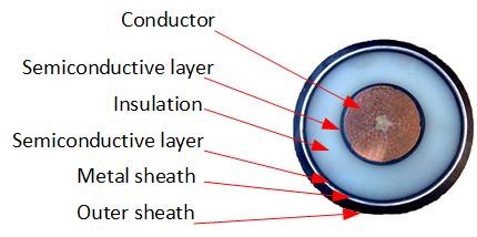
Figure 1 - Example of single core HV/EHV cable
Content
In the Technical Brochure, different types of cable arrangements and installation are covered. Tunnels, open trench, ducts, HDD, ploughing and offshore installations are considered. Special safety precautions and appropriate equipment are indicated for different setups.
This Technical Brochure references the risks associated with induced voltage on cable systems only; it does not appraise or scrutinise other possible safety issues associated with other hazards on cable systems, such as mechanical stresses etc...
In Chapter 1, the Technical Brochure starts by discussing and identifying the induced voltage phenomenon which can have several origins.
With the purpose of identifying what is a hazardous environment due to induced voltages or currents, there is a need for identifying the limit of touch voltages. As this varies from country to country, and as there are several different standards discussing the topic, the task of the Working Group B1.44 has included an in-depth appraisal of these standards and guidelines and a thorough consideration to what should be recommended and included in appropriate International Standard.
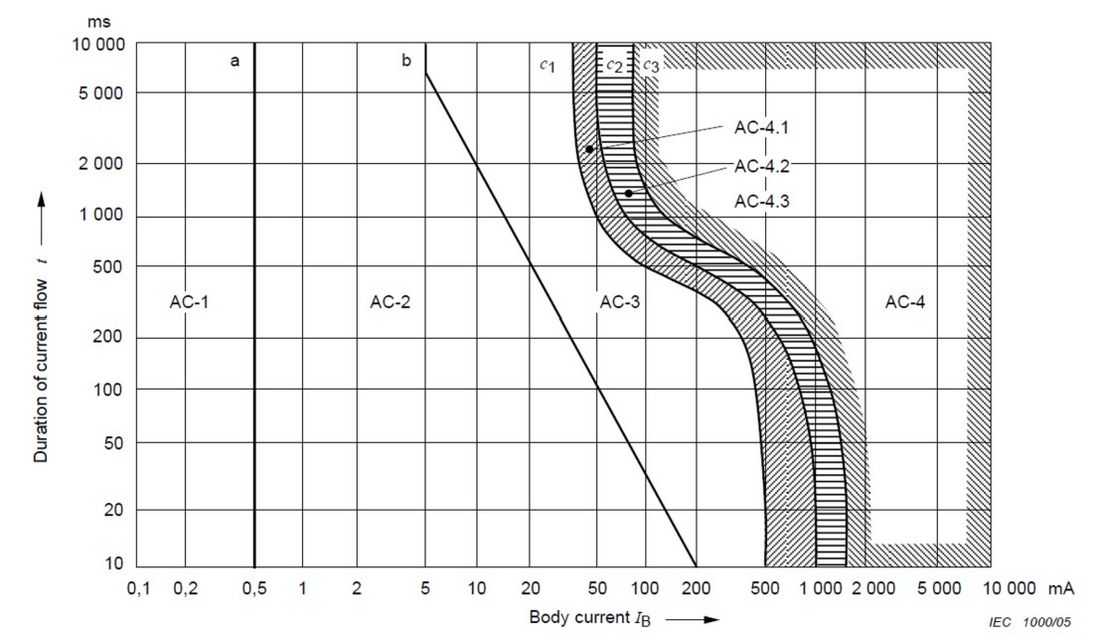
Figure 2 - Time/Current curves of effect of AC current through the human body [IEC 60479]
Induced voltage mechanisms
The basic principle underlined in the guide, is that before the start of any work on power cable systems, it is highly recommended that a risk analysis and the calculation of possible induced voltages be carried out. This suggested risk analysis is explained in the Principles of Safe Work in Chapter 2. Three different principles of safe work are given and detailed: Earthed working without currents (which is the recommended method), earthed work with currents and insulated working.
In Chapter 3, a detailed summary of safe working procedures is given for several stages of work on cable systems: laying/pulling, cutting, jointing, terminating, testing, removal. It is reminded that all these works must be carried out by qualified and certified personnel only.
Chapter 4 provides the calculation methodology of the three different types of induced voltages. Some real examples on cables systems experiencing induced voltages, from different countries, are detailed in appendices. Conclusions and recommendations are given in Chapter 5.
Induced voltage mechanisms
There are several types of induced voltages that can affect the potential of the cable core, screen and metal sheath. According to previous CIGRE Studies, the different types can be divided into three categories depending on how they are coupled from an electrical source to the object of induction.
- inductive coupling
- capacitive coupling
- conductive coupling
All three issues must be evaluated when dealing with induced voltages. The influence from each coupling depends on the presence of other electrical systems in the surroundings of the cable, and how the cable system is bonded to earth.
Inductive coupling
An insulated conductor which runs in the proximity of a power line or a cable, either on the full route or on a part of its route, is subject to voltages induced by magnetic coupling.
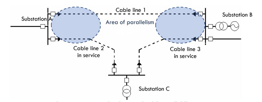
Figure 3 - An example of network with parallel lines
The coupling is due to time-varying magnetic flux from the source of the induction being linked with a circuit formed by the conductors of the object of the induction.
Current in a nearby cable or overhead line (OHL) in service, whether it is during normal conditions or due to fault conditions, will induce voltage longitudinally on the insulated conductor (which is either being installed, repaired or maintained). If the distance is small, and especially if there is asymmetric current in the system in service (for instance short circuit current due to a fault) the induced voltage can become several kilovolts. This induced voltage will be longitudinally on all metal parts of the cable whether in or out of service, i.e. armour, metal sheath, conductor and parallel earth wires (such as Earth Continuity Conductors, ECC).
The magnitude of the induced voltage, due to inductive coupling, depends on the current in the source system, the distance between the two systems and the length of parallelism of the two systems. It should be noted, that the magnitude of the inductive coupling induced voltage is independent of the systems voltage level.
Capacitive coupling
Capacitive coupling is the result of electric field around an energised power system. The electric field is associated with a capacitance between the source and any un-earthed conductive object exposed to the field. Together with the capacitance between the un-earthed object and earth, a capacitive voltage divider is formed, so that for an alternating voltage source, a proportion of the source voltage appears on the object.
Therefore, overhead lines or substation busbars can only influence insulated cables that are not shielded neither by the earth nor by an earthed screen. This influence occurs in both normal operation and fault conditions.
On the opposite, underground and offshore cables cannot generate capacitive coupling as the electric field is contained inside the shielded insulation.
Power frequency voltages appear between the insulated conductor of the cable and the earth; their magnitudes depend mainly on the voltage level of the OHL, the distance between OHL and the insulated conductor, and on the OHL operating conditions (normal operation or faults). It should be noted, that the magnitude of the capacitive coupling is independent of the current flowing in the systems.
Whenever a cable is left disconnected, the metal sheath and core conductor should be shunted and locally earthed, to prevent standing voltage. It should be noted that only a part of the cable system needs to be exposed to the electric field for the whole cable to be affected.
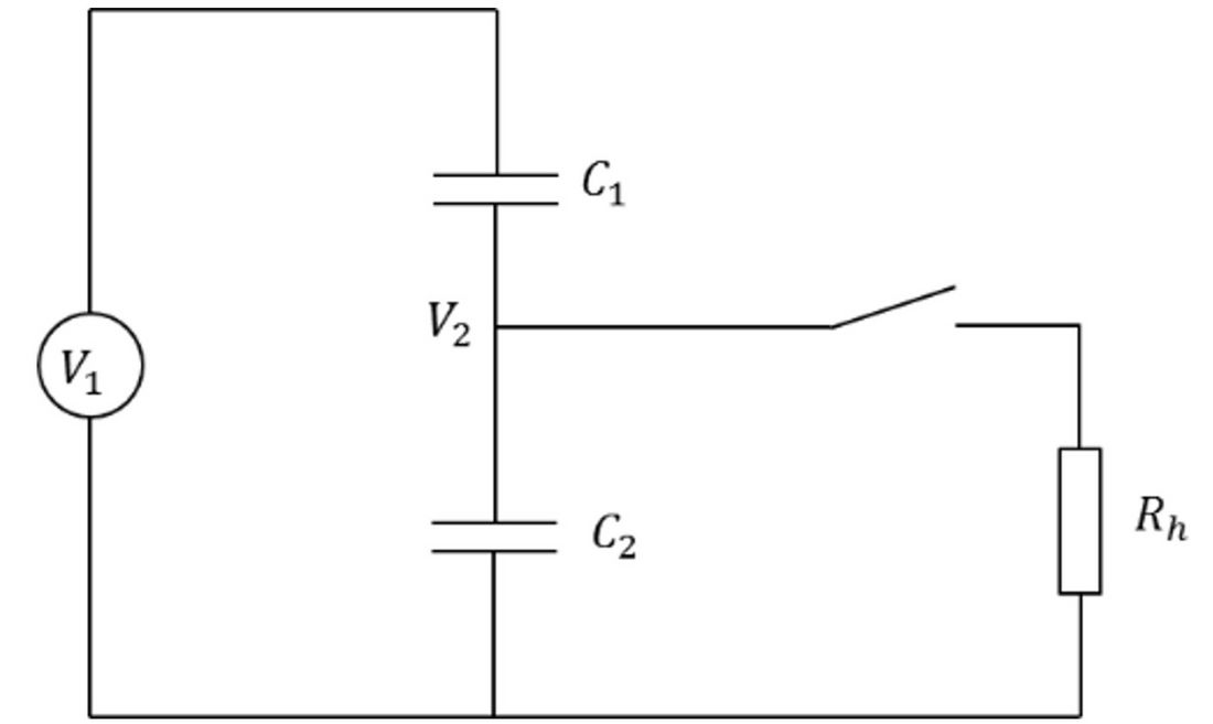
Figure 4 - Simplified circuit of capacitive coupling
Conductive coupling
Earth currents (such as fault return currents) flowing through the earthing impedance of an earthing system (such as a tower, substation, at jointing bays or power plant) produce an Earth Potential Rise (EPR) of the earth system with respect to any remote earth. Conductors connected to that earth system can transfer the potential rise to any other earth system where they may be connected, which may be many kilometres away.
Cable systems often connect two different earthing systems (between different substations, for example). In such situations, consideration should be given to the transfer of EPR. The situation already exists on normal operation of HV systems (where EPR is created by induced currents or stray currents) and is aggravated when there is a fault on one part of the system that will cause EPR at the location. The cable will transfer this rise of earth potential to another location that has a different earth potential. Therefore, there can be a voltage difference between two “earthed” objects, one earthed locally and the other remotely.
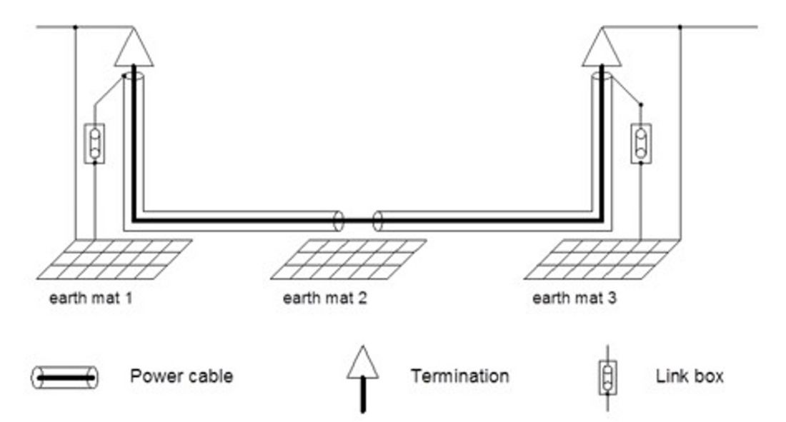
Figure 5 - Cable system between different earthing systems
Principles of Safe Work
When installing a new cable circuit or when working on an existing cable system there may be an imminent safety hazard due to dangerous induced or transferred voltages and/or heavy circulating currents even though the cable to be worked on is disconnected and isolated from electrical system and earthed.
It is important to be aware that while it may be safe to work on an out-of-service insulated cable under normal system/grid operation conditions, dangerous voltages can occur unpredictably at any time due to external faults in electrical system or due to switching, lightning or other voltage surges.
As a result, it is imperative that when planning work under influence of induced voltages the developed working procedures must include an assessment of safety hazards (electrical risks) and to implement the most suitable safe working conditions by considering the three basic safe working principles:
- earthed working with currents
- earthed working without currents
- working insulated (with induced or standing voltage)
For each working principle, detailed illustrations and appropriate tools are presented.
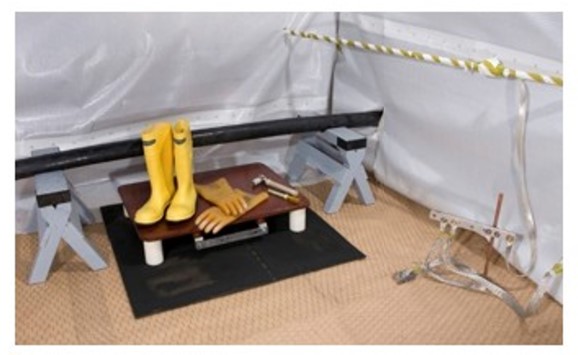
Figure 6a - Example of workplace and protection equipment for insulated working
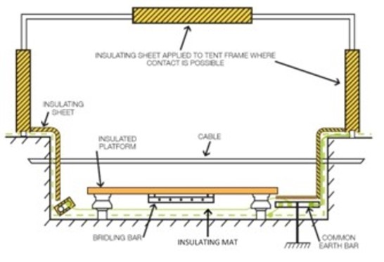
Figure 6b - Principles for working place prepared for insulated working
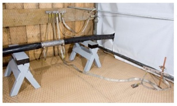
Figure 7a - Example of a workplace with proper equipotentiality and earthing on metal sheath using earthing leads
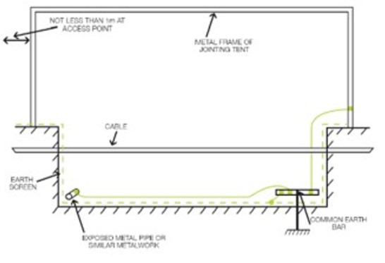
Figure 7b - Example of a workplace where earthing is prepared for the work procedures
Before carrying out any operation on an electrical installation, an assessment of the electrical risks shall be made. This assessment shall specify how the operation shall be carried out and what safety measures and precautions are to be implemented to ensure safety.
If a cable system is fully or partly parallel to another underground cable (UGC) or OHL in operation, a special attention must be given during the handling.
The estimate of induced voltages and potential rise of the soil may be obtained analytically by using equations detailed in Chapter 4 or by modelling. The electrical parameters, current and voltages, must be calculated in the steady state conditions and under emergency conditions (short-circuit, lightning and switching surges). Several cases should be taken into account following the type of fault events that may happen in the neighbouring power lines. To validate the model, it is advised to perform some measurements on site. Where it is not possible to accurately calculate the induced voltages due to inaccurate information about the external factors or unknown factors, the worst-case scenario should be adopted for calculation.
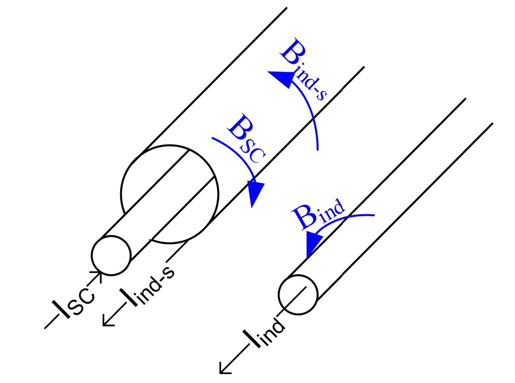
Figure 8 - Principles of magnetic coupling
In the case of induced voltages or EPR above the maximum allowed induced voltage, the risk analysis should also include a recommendation on how to perform the work safely. This recommendation should give the maximum size of possible earthing resistances to reduce the induced voltages, the current rating for the earthing connections and a proper step-by-step description of the physical work. For jointing and termination work, the proper work procedures ensuring safety and earthing should be requested from the person responsible of the work. Prior to starting any work, it is important to ensure proper equipotentiality and earthing. If it is not feasible to work with equipotentiality or if there is a requirement for insulated working, the type and level of insulated tools should be described in the risk analysis.
Conclusions and recommendations
This Technical Brochure presents and discusses several aspects of induced voltages on power cable systems. Three types of induced voltages have been considered; (i) - inductive coupling, (ii) - capacitive coupling and (iii) - conductive coupling (EPR).
The focus of this Technical Brochure is on how to calculate induced voltages on the cable to be worked on, how to plan the works in case of induced voltages and how to proceed with the work in situations where there is a risk of hazardous voltages or currents.
Assuming that there is a risk of induction, two main principles of safe work are introduced; i.e. the “Earthed work” and “Insulated work”. For the earthed working conditions, it is possible to apply either earthed working without currents, where there is only an earth connection made locally at the workplace or, to apply earthed working conditions with currents, where the cable is also connected to earth at the cable far ends. In both cases, equipotentiality at the work area must be ensured first.
Throughout the Technical Brochure, all principles are addressed, but the brochure recommends earthed working conditions without currents as a primary solution to ensure safe work where there is a risk of induced voltages either by inductive coupling, capacitive coupling or EPR.
In any case, all installation works under induced voltage, should always be carried out by qualified and certified personnel only and following local legal requirements if available.
In the Appendices of this Technical Brochure are included several examples of how to perform induced voltage calculations and several actual case studies from different countries.
One of the important findings that have been identified, is that there is no clear guidance or an appropriate standard for the evaluation of maximum permissible touch voltage for cable systems outside of substations. As a result, in this Technical Brochure are cited several standards and guidelines which are related and used in different countries. Furthermore, in this Technical Brochure is included a recommendation to IEC to update the existing standard IEC 61936, where are given the limits of touch voltages as a function of clearance time, for cable systems within substations. The recommendation is mentioned in Chapter 1 and explained further in the first appendix.

Other Technical Brochures