Recommendations for a performance guideline of Solid Insulated Busbars
Solid Insulated Busbar (SIB) is a kind of fully insulated current-carrying device with a rigid conductor using solid dielectric material as the insulation. It has numerous advantages, such as large capacity, small space occupation, and high environmental adaptability, and has been widely used around the world. This technical brochure contains information on the design, testing, manufacture, installation, operation, and maintenance of current SIBs, as well as proposals for SIB test techniques and SIB standard series recommendations.
Members
Convenor (CN)
J. FAN
Secretary (FR)
P. MIREBEAU
SC B1: R. LIU (CN), F. MICHON (FR), S. C. GEDELA (DE), C. PETRARCA (IT), S. DYBALLA (CH), P. KNAPP (US)
SC B3: D. PLATT (AU), L. RUAN (CN), Z. WU (CN), K. HELAL (FR)
Corresponding Member: I. JHONSTON (UK)
Introduction
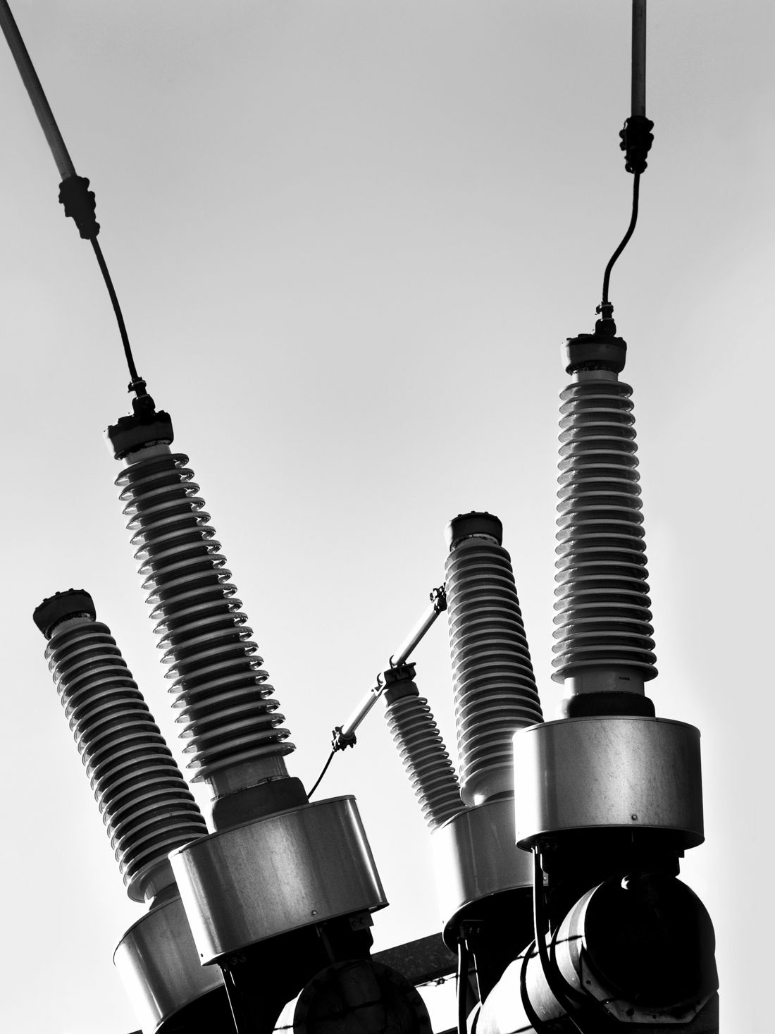
Solid Insulated Busbars (SIB) were first developed in the 1970s and have a rigid conductor like conventional busbars or GILs and a solid dielectric insulation structure like insulated cables, providing full insulation, high current-carrying capacity, small space occupation, environmental adaptability, and ease of operation and maintenance. Consequently, this type of equipment has been widely used in traditional and various new energy power plants, power grids and customer substations, large building power supply systems, with the development trend of replacing open-insulated busbars, power cables, and GIL in certain application scenarios.
This Technical Brochure (TB) provides information on the design, testing, manufacture, installation, operation and maintenance of existing SIBs, recommendations for SIB test methods, and recommendations for the SIB standard series.
Scope and Methodology
The Joint Working Group B1/B3.74 was established in November 2019 as an answer to an IEC (International Electrotechnical Commission) request, to gain a more comprehensive understanding of the technical characteristics of the SIB and the present status of its research and use in order to provide specific proposals for the standardisation of this device. The scope of work consists of the following:
1. Present use of solid insulated busbars
- Review of manufacturers, product types and applications worldwide
- Review manufacturers proprietary tests
- Basic design description of the SIB
- Definitions of the different SIB components.
2. Pre-standardisation document structure and main contents
- The main considerations of SIB pre-standardisation
- development, performance, qualification tests
- Guidance on after installation tests
- Guidance on the maintenance of SIBs.
Note: The name of the object of this JWG has been changed from “polymer insulated busbar (PIB)” to “solid insulated busbar (SIB)” to include impregnated paper insulations. So, the JWG’s name should be changed to “Recommendations for a performance guideline of Solid Insulated Busbars”.
To review the state of the art, a survey was prepared for utilities, research institutes and manufacturers, focusing on design, test procedure, manufacturing, operation, and maintenance procedures, as well as proposals for standardisation. The survey yielded responses from SC B1 and SC B3 members, as well as some industry participants via JWG members.
Description of the Technical Brochure (TB)
Historical overview
Historical overview of the developments of SIBs is provided in Chapter 1.
Terms and definitions related to the SIBs
Chapter 2 includes the words and definitions relevant to SIBs and used in this TB, such as the fundamental principles, system and components, design, test, and operation and maintenance. Some of these terms and definitions were first proposed by this TB. Terms and definitions in regional SIB standards, technical standards for power cables, bushings, switchgear, insulators, and other similar equipment were taken account.
Since the vocabulary associated with SIB devices and even its name is not universally standardised, this chapter will assist readers in comprehending this TB and provide a pre-standard text for the terms and definitions pertaining to this type of equipment.
Survey and analysis
Chapter 3 presents the questionnaire work conducted by the JWG and its results. The questionnaire intends to collect the experiences and recommendations of SIB-related designers, testers, manufacturers, users, and researchers from worldwide. It consists of more than one hundred questions divided into five sections: design, testing, manufacturing, operation, and maintenance.
From May to August of 2020, 27 feedbacks were returned. The comments were incorporated into the relevant portions of the TB. In addition, this research found that SIB is not well understood by the majority of specialists, and many SIB-related terms, such as the component names, are readily misinterpreted due to a lack of standards and consensus. Consequently, the present JWG work is necessary.
Design of the SIB
Chapter 4 presents the design issues of SIBs. It includes the classification of SIBs, system components and main parts, accessories and appurtenances and their structures, key design parameters, etc.
Among them, this TB presents 4 common types of SIBs.
- Resin impregnated paper insulation type - employs crepe paper that has been appropriately dried and vacuum-impregnated with cast epoxy resin in order to achieve good dielectric and mechanical strength, as well as suitable dielectric loss properties.
- Extruded insulation type – is comparable to single core power cables, typically employing insulating materials such as polyethylene (PE), silicone rubber (SIR), or Ethylene-Propylene Diene Monomer rubber (EPDM).
- Tape-wrapped insulation type – uses Polytetrafluoroethylene (PTFE, Teflon) or Polyester Tape (PET) films as insulating materials and are wound on the tube-shaped internal conductor.
- Cast-resin type - consists of rectangular copper or aluminium conductors encapsulated in an epoxy resin composite exhibiting suitable mechanical and dielectric qualities.
A further aspect of SIB design is that the length of a single conductor typically does not exceed 10 meters. This typically...
ELECTRA, is the digital magazine of CIGRE, you can obtain access as part of a CIGRE membership. Find out more about joining options here.
Other Technical Brochures