Recommendations for dielectric testing of HVDC gas-insulated cable connection assemblies
HVDC transmission systems are key enabler in the energy transition, connecting renewables and load centres through long distance and high-capacity links. Minimisation of the footprint required is particularly relevant for HVDC equipment as it is often applied in space constrained locations. For this reason, HVDC gas-insulated systems have been developed by several manufacturers including metal-enclosed HVDC GIS cable connection assemblies, the qualification of which has been a subject of discussion due to a mismatch between the recommended test approaches for cable and GIS technologies. This technical brochure provides recommendations for the dielectric testing of HVDC GIS cable connection assemblies based on a comparison of the simulated electric field strengths resulting from cable system and GIS test approaches.
Members
Convenor (CA)
C. PLET
Secretary (DE)
M. KOSSE
S.ALAPATI (SE), N.LALLOUET (FR), F.JACQUIER (FR), U.RIECHERT (CH), T.KARMORKAR (DE), F.MICHON (FR), H.HE (NL), H.YE (DE), C.BEVERWIJK (NL), D.BOA (UK), M.YAGI (JP), L.HOEFER (DE), J.STRIDE (UK), K.ZHOU (US), M.ALBERTINI (IT), D.CISILINO (CH), G.SUN (CH)
Structure
The Technical Brochure is the result of the work of CIGRE joint working group B1/B3/D1.79 “Dielectric testing recommendations for gas-insulated HVDC cable connection assemblies”. It is a summary of the technical brochure which will be published in 2024. The working group was made up of 19 members representing HVDC cable system, accessory and GIS manufacturers, TSOs, developers, testing laboratories and consultants from Asia, Europe and North America.
The Technical Brochure is organised as follows:
- Chapter 2 provides an overview of the applications, foreseen benefits and state-of-the-art of gas-insulated HVDC cable connection assemblies. Typical operational stresses and the currently available testing standards for HVDC cable systems and HVDC GIS are discussed and compared. A view is provided on future developments in HVDC technology and applications and how these might affect HVDC GIS cable connection assemblies
- Chapter 3 presents thorough simulation-based analysis of the dielectric stresses on cable connection assemblies resulting from test requirements in existing HVDC cable system and HVDC GIS standards. The results from both open-source models and commercially available designs are discussed and compared to a comprehensive sensitivity analysis
- Chapter 4 contains a complete set of dielectric testing recommendations for HVDC GIS cable connection assemblies for all life cycle phases, and comments on the interoperability of designs from different vendors in the context of qualification testing.
- Chapter 5 summarizes the conclusions of this Technical Brochure
- Chapter 6 provides suggestions for further research and/or future Working Groups.
- Appendix B contains a detailed guideline for the modelling and simulation of the dielectric behaviour of HVDC GIS cable connection assemblies
Introduction
To minimise footprint, HVDC gas insulated systems have been developed by several manufacturers, qualified and brought to market, including a metal-enclosed HVDC GIS cable connection assembly in the product range for the 320 kV, 400 kV and 500 kV voltage classes. The designs have been qualified using the test requirements of CIGRE Technical Brochure 496 'Recommendations for testing DC extruded cable systems for power transmission at a rated voltage up to 500 kV'. The qualification of HVDC GIS cable connection assemblies has been a subject of discussion due to a mismatch between the recommended test approaches for cable and GIS technologies. Testing of HVDC cable systems with extruded polymer insulation has been addressed by CIGRE TB 852, whereas testing of HVDC gas insulated systems is addressed by the CIGRE TB 842. Neither documents provide instructions on how to test the GIS-cable interface. This Technical Brochure provides recommendations for the dielectric testing of such HVDC GIS cable connection assemblies based on a comparison of the simulated dielectric stresses applied as a result of both cable system and GIS tests.
Background
State of the art
The following sections report on the results of a supplier survey conducted with six HVDC GIS cable connection assembly manufacturers, reflecting the status of development in March 2021
General arrangements - Typical arrangements of the resulting 'fluid-filled' and 'dry-type inner cone' cable connection assemblies were reported and are shown in Figure 1.
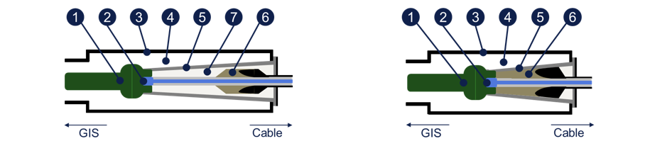
a) Fluid-filled b) dry-type inner cone
Figure 1 - Typical general arrangements for gas-insulated cable connection assemblies
The main components in a cable connection assembly are as follows:
1 | Switchgear connection interface (GIS electrode) | 5 | Separating Insulator |
2 | Cable termination connection interface (shielding electrode) | 6 | Electrical stress control component |
3 | Cable connection enclosure | 7 | Insulating fluid (gas) |
4 | Gas |
|
|
Components 1 and 2 together make up the main circuit end terminal (MCET).
Test philosophies comparison
The testing recommendations provided in the CIGRE TB 842 and CIGRE TB 852 Brochures differ on the following key points:
- Cable tests aim to provide proof of sufficient lifetime whereas HVDC GIS tests provide proof of the GIS’ ability to withstand operational stresses
- HVDC cable current ratings are typically much lower than that of HVDC GIS
- Recommended HVDC cable continuous testing voltages are significantly higher than the recommended continuous testing voltages for HVDC GIS and would lead to different charging behaviour of the HVDC GIS insulators
- Conversely, recommended impulse testing voltages for HVDC GIS are significantly higher than that of HVDC cable systems and can damage the cable system insulation
Test voltage definition
From an analysis and comparison of the test approaches for both HVDC cable systems and HVDC GIS, it follows that in both cases the test voltages are derived by multiplying the rated voltage by test factors. However, two difficulties exist which complicate the derivation of test values for HVDC GIS cable connection assemblies.
- HVDC cable and HVDC GIS standards/Technical Brochures use different definitions of 'rated voltage'
- For the 500 kV voltage class, both HVDC cable and HVDC GIS industries appear to have adopted different 'standard' nominal voltages of 525 kV and 500 kV, respectively, as U0 for HVDC cables and Un for HVDC GIS
As a result of these differences, even when adopting the same test factors, the test voltages resulting from applying the HVDC GIS test standard would be different from that of the HVDC cable test standard due to the different base values.
Analysis
The dielectric stress of commercially available HVDC GIS cable connection assembly designs were simulated to assess whether the test requirements for HVDC cable systems lead to higher internal stresses than those for HVDC gas-insulated switchgear. The simulations were carried out by several vendors using finite element methods according to a common Modelling and Simulation Guideline (appendix B in the Technical Brochure) to ensure consistency of the results. In addition, simulations were carried out using an open-source benchmark model to verify the modelling guideline, to study simplifying assumptions and to carry out a sensitivity study on the impact of tolerances in real life test environments. All dielectric qualification tests from CIGRE TB 842 and TB 852 were considered for simulations and reduced in number by applying simplifying assumptions.
ELECTRA, is the digital magazine of CIGRE, you can obtain access as part of a CIGRE membership. Find out more about joining options here.
Other Technical Brochures