Methodes for identification of frequency response characteristic of voltage measurement systems
The Technical Brochure of WG A3.45 deals with the technology of voltage measurement systems, which are covered by the standard family IEC 61869. First, an overview of all voltage measurement technologies is discussed in detail for conventional voltage transformers and low-power voltage transformers for the rated frequency and based on that, the higher frequency performance is derived. The modern requirements of the grid versus the performance requirements of secondary equipment are the basis for the required performance of the voltage measurement system. To characterise the intended voltage measurement technology, the brochure provides, on the one hand, detailed mathematical modelling concepts, and on the other hand, necessary measurement methodologies in order to be able to evaluate and test voltage measurement systems. The brochure finally provides a detailed overview, summarised in a table which allows for identifying the correct measurement technology to be used depending on grid requirements in terms of disturbance phenomena and applications. Also, performance parameters, assessment criteria, transfer characteristics and influence factors on the behaviour of various voltage measurement technologies are presented and discussed.
Members
Convenor (CH)
E. Sperling
Secretary (CH)
M. Freiburg
R. Schulze (DE), G. Crotti (IT), A. Fanchet (FR), M. Nadeau (CA), G.H.C. Oliveira (BR), Th. Laughner (US), R. Stiegler (DE), J. Meyer (DE), J. Rickmann (DE), P. Chaves (CA), F. Rahmatian (CA), A.M. Blanco (DE), J.A. Filho (BR), F. Wanh (CA), H. Reader (ZA), H.J. Vermeulen (ZA)
Introduction
The energy transition and the related extension and modernisation of electricity grids affect many areas of the power system, including the introduction of new primary and secondary technologies, additional equipment stress, larger dynamic operational ranges, higher distortion levels, additional metering points and so on. Voltage measurement systems are the interface between a changing primary power system and the secondary connected application, such as metering, monitoring, protection, automation and control. They can be seen as the eyes and the ears of the electric grid. The new environment changes the requirements on instrument measurement systems accordingly. Voltage signals ranging from DC to high frequencies, including transients, can be found in the electric grid, as shown in Figure 1.
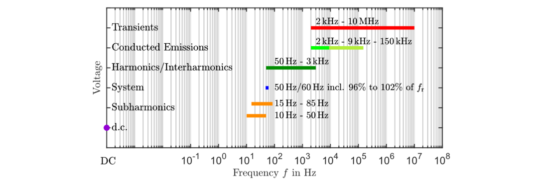
Figure 1 - Signal frequency spectrum in electric grids - Extended measurement requirements for voltage measurement systems
To be able to choose the correct measurement system, it is crucial to understand first the measurement system itself, but also to identify the new requirements and performance characteristics. Therefore, it is crucial to measure not only the grid voltage at rated frequency but also at lower and higher frequencies.
For more than 100 years, conventional instrument transformers (ITs) have provided analogue output signals as a standard value. For at least 2 decades, modern ITs have also provided digital output signals. Merging units (MU) offer today, on the one hand, the digitisation of analogue values and also merge those signals with other digital signals to be used in digital substations based on standard IEC 61850-9-2.
Voltage Measurement Systems
Today, two different types of instrument transformers exist as per the definition of the relevant standard. The first group represents the so-called conventional voltage transformers, which are inductive voltage transformers (VTs) and capacitor voltage transformers (CVTs). The other group is designated as low-power voltage transformers (LPVTs) and is represented by voltage dividers and optical voltage transformers. All discussions are based on the standard voltage measurement at the nominal frequency.
In Chapter 2, first, the fundamental magnetic coupling relation is presented as a basis for the following descriptions. For the VTs and CVTs, design principles are provided on a very detailed level. Standard models for accuracy calculation are introduced, and accuracy-dependent factors are listed and discussed. All the relevant equations are shown and explained in detail. The technical design with a focus on measurement precision always follows the same approach.
- Determination of the ratio based on the primary and secondary voltage levels
- Considering the magnetic coupling using an iron core and the corresponding magnetisation curve
- Determination of the impact of individual elements of the defined equivalent circuit diagram on the overall precision.
Calculation examples show how the ratio error and phase displacement can be calculated and influenced by varying parameters.
Furthermore, LPVTs are listed and discussed. The six important voltage divider types, see Figure 2, are described on a detailed level with the focus on technical design, application-related design principles, model descriptions and corresponding relevant equations. Environmental impact factors on the overall precision are discussed, and calculation examples of the measurement performance are provided.
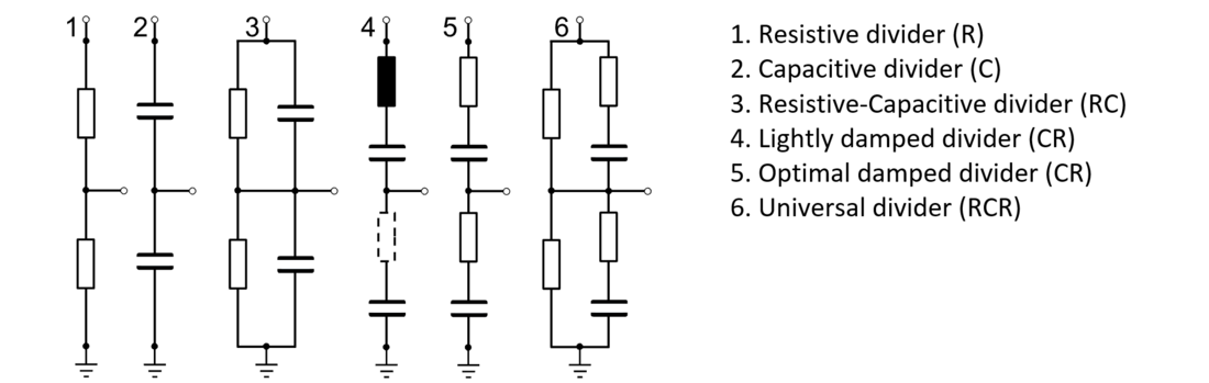
Figure 2 - General overview of divider categories
The second type of LPVT represents the optical voltage sensor based on the Pockels Effect. A description of the primary sensor and the principal design is provided. In addition, modelling is presented and discussed, and practical considerations are provided.
ELECTRA, is the digital magazine of CIGRE, you can obtain access as part of a CIGRE membership. Find out more about joining options here.
Other Technical Brochures
