Analysis and Comparison of Fault Location Systems in AC Power Networks
Rapid and precise location of line faults is becoming more important in modern AC power systems. Outage times because of permanent faults need to be reduced and accurate identification of the position of faults is necessary for proper power system operation. For those faults that successfully reclosed, accurate fault locating allows preventive maintenance to be undertaken to avoid occurrence of faults at the same location. Getting to the fault site fast and being able to accurately correlate results with lightning data, vegetation burnings, and other phenomena greatly assists identification of the root cause when flashovers occur, an important parameter when reporting to the regulator.
Convenor
(SE)
S. SEFIDPOUR
Secretary
(US)
A. MONTENEGRO
D. SPOOR (AU), M.A.M. RODRIGUES (BR), SH. SHI (CN), A. VAINIONPÄÄ (FI), S. MAMODALY (FR), F. RIOS (SE), V. TERZIJA (UK), A. GUZMAN (US)
Corresponding Members: ZH. LI (CN), A. WAHLROOS (FI), T. MIYOSHI (JP), A. BAJRACHARYA (NZ), CH.S. MELAAEN (NO), M. DRAGOMIR (RO), A. PODSHIVALIN (RU), P. KELLER (ZA), D. COLE (UK), Y. DONG (US), J. GOSALIA (US), R. DAS (US)
Introduction
Different fault locating methods require very different levels of investment; several methods were reported to this working group from 40 utilities around the world. They ranged from simple, low-cost solutions to more expensive, sophisticated systems utilizing multiple techniques to improve performance.
From the fault locating methods available today, impedance-based and travelling-wave-based techniques are the most used in transmission and sub-transmission AC networks. However, use of faulted circuit indicators (FCIs) and line patrols still dominate fault locating techniques in distribution applications.
Fault locators based on impedance and travelling-wave techniques rely on digital technology to process acquired voltage and/or current signals from instrument transformers and their interfaces. The acquired signals are processed either locally on the installed device for single end measurements or centrally when communication channels are used to collect data from different sources.
Each fault locating technique has its own advantages and disadvantages when applied to different power network topologies. Methods utilizing time synchronized/unsynchronized data from multiple points/terminals are usually preferred. The emergence of cost-efficient communication solutions and increasing digital computing power enables utilities to maximize the performance of these more sophisticated techniques to provide more accurate results in shorter time at the substation or control centre location.
For utilities to implement an appropriate fault locating system, it is important to have knowledge of the different established techniques and their application to different power network topologies. This technical brochure explores commonly used fault locating techniques and presents practical aspects to those implementations in different applications. Enhancing fault location accuracy by incorporating geographical and environmental data, operational considerations based on fault location results, and future trends in fault locating techniques have also been considered in this brochure. The results of the survey conducted by this working group are presented at the end of the document.
Structure of the Technical Brochure
The Technical Brochure includes the following chapters:
- §1 introduces the fault locating challenges and potential sources of errors, such as fault resistance, inaccuracies in line parameters, instrument transformers, system nonhomogeneity, and so on.
- §2 reviews known and well-established fault locating techniques. The chapter describes in detail approaches based on fault impedance measurements, travelling waves, faulted circuit indicators, and line patrol.
- §3 provides implementation details and application considerations, addressing the issues related to instrument transformers, multi-end lines, homogeneous and non-homogeneous circuits, series compensation, line transposition, as well as typical aspects relevant to distribution networks. The chapter also includes actual field data and waveforms to explain the different fault locating techniques.
- §4 presents the use of geographic maps, including information from lightning tracking systems and vegetation fires, to support fault locating activities
- §5 addresses operational considerations based on fault location results, such as automatic reclosure.
- §6 presents future trends that use centralized model-based fault locating methods.
- §7 presents the results on existing fault locating practices according to the responses of the 40 surveyed utilities.
- §8 provides the conclusion including recommendations to improve fault locating systems.
Fault Locating Methods
Impedance- and travelling-wave-based fault locating methods are the most commonly used methods in transmission line applications. When these methods use measurements from all the line terminals and absolute time synchronization, they provide accurate fault location results. Following is the description of double-ended methods with absolute time synchronization.
Double-Ended Impedance-Based Method
The simplest double-ended algorithms require voltage and current phasors acquired at the line ends, which are time synchronized using a Global Navigation Satellite System such as GPS or other similar systems. For circuits where the voltage and current phasors (and hence the symmetrical components) are synchronized, a simple double-ended algorithm can be adopted. This technique recognizes that the voltage along the line can be represented as a function of the distance to the fault. If there is only one fault, two equations can be generated from the line ends, equated, and solved. Consider the faulted network from Figure 1. Assuming that the measurements are synchronized, equations (1) and (2) define the voltage VF at the fault point F, as observed from each end of the line.
VF = VS – mZLIS (1)
VF = VR – (1–m)ZLIR (2)
where ZL is the line impedance, and VS, VR, IS and IR are the voltages and currents at the line ends.
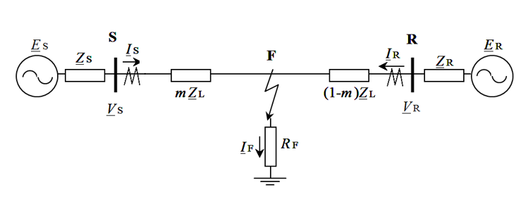
Figure 1 - Simple two-machine network with a fault
Equations (1) and (2) can be solved for any of the sequence parameters, although it is usually best to use positive-sequence values to determine the fault location m, as given by (3).
m =│(VS1 – VR1 + ZL1IR1) / ZL1ID1│ (3)
where ID1 = IS1 + IR1 is the differential current, VS1 and IS1 are the positive-sequence voltage and current at terminal S, and similarly, VR1 and IR1 are the positive-sequence voltage and current observed at terminal R.
This method is highly sensitive to the error of phasor synchronization. Phasors from both line ends should be time synchronized. A time offset and a consequent phase shift may result in distance estimation error. It is generally accepted that phase (angle) error should not exceed 3 degrees.
Double-Ended Travelling-Wave-Based Method
The most popular traveling-wave-based method is the double-ended method with time synchronization at the line ends, which requires the use of a Global Navigation Satellite System such as GPS. Additionally, one or more communication channels might be required to allow the data from the two recording stations to be brought to a central location (if applicable) or one of the line ends. When a fault occurs, both travelling wave devices record the arrival time of the initial transient pulse. The arrival times TS and TR are shown in Figure 2. The fault location is then determined from the time difference between these two recorded wave fronts.
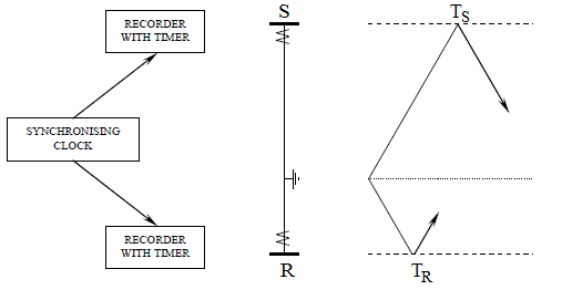
Figure 2 - Double-ended travelling wave fault location system
The distance from terminal S can be calculated from (4) and the distance from terminal R can be calculated from (5).
mS = L/2 + ∆T·(v/2) (4)
mR = L/2 – ∆T·(v/2) (5)
where L is the length of the line, v is the travelling wave propagation velocity of the aerial mode, and ∆T is equal to TS minus TR.
Utility Survey on Existing Fault Locating Practices
The survey includes information of 40 utilities from countries in different continents. Thirty-three of the surveyed utilities are transmission system operators (TSOs), four are distribution system operators (DSOs), and three are TSO/DSOs. Here is a summary of the survey results:
- The average number of people involved in fault location analysis is six persons. One of the companies reported that 40 people work on fault locating activities.
- The most common earthing methods are solidly earthed for transmission systems and impedance (resistive or inductive) earthed for distribution systems.
- Single-ended impedance is the most used fault locating method in transmission and distribution networks.
- Fault location analysis is performed in 100 percent of permanent faults and 84 percent of temporary faults.
- The most common relative accuracy requirement is five percent and absolute accuracy requirement is two kilometers.
- The most common absolute accuracy requirement for travelling-wave-based fault locators is one kilometer.
- Many of the utilities require the fault location information as soon as possible. Other utilities require the information in less than 30 minutes, less than one hour, or less than 24 hours.
- When using the impedance method, 83 percent of the utilities use the method available in protection relays.
- When using the travelling-wave-based method, 82 percent of the utilities use stand-alone fault locator.
- Utilities reported that the most accurate method is the double-ended travelling wave method with accuracies better than 300 meters.
- Some of the sources of problems are communications, time-synchronization, wrong settings, and network topology changes.
Conclusion and Recommendations
Typically, initial fault location estimations are obtained from protection relays, fault recorders, and stand-alone fault locators. When these estimations are inaccurate, manual analyses are required to obtain improved estimation results. If applicable, these analyses should consider all available fault locating techniques which may be relevant to the network topology of the line under study and should include correlation with geographical and environmental data and even customer report data. Moreover, the performance of any of the fault locating techniques depends on the accuracy of the line model, measurement errors, fault resistance, and other factors.

Other Technical Brochures