On-Site Assembly, On-Site Rebuild, and On-Site High Voltage Testing of Power Transformers
The aim of the Working Group was to address the new challenges presented by on-site assembly, on-site rebuild, and on-site high voltage testing. New work techniques for large power transformers had to be developed in many countries due to restrictive transportation regulations. This Technical Brochure shows, by way of a collection of international experiences, some of the best practices and it summarizes the quality assurance system required to ensure the reliability of on-site work.
Convenor
(JP)
Y. SHIRASAKA
Secretary
(JP)
T. HASEGAWA
E. TENYENHUIS (CA), J. SZCZECHOWSKI (DE), P. WERLE (DE), M. RAMKVIST (SE), T. GONÇALVES (PT), R. FRITSCHE (DE), R. PETIT (FR), T. NOONAN (IE), K. AOKI (JP), S. YAMADA (JP), T. TANAKA (US), Z. ZHAO (CN)
Corresponding Members: K. YAMAGUCHI (JP), S. NOGUCHI (JP)
Scope
The terms of reference of the Working Group included:
- To perform a survey of international experiences and best practices for on-site assembly, on-site rebuild, and on-site high voltage testing.
- To describe applications and case studies as well as alternatives approaches to reduce mass and dimensions such as two smaller three-phase transformers in parallel or three single-phase transformers.
- To discuss design and construction issues related to site assembly.
- To present dis-assembly and re-assembly issues, mainly for on-site assembly but also on-site rebuild.
- To provide a typical scope of work, mainly for site-assembly.
- To describe applications and case studies for on-site high voltage testing, including the limitations of currently available technologies.
- To consider any additional requirements for pre-commissioning and trial operation.
Summary of the Technical Brochure
Site Assembly of large transformers was shown to be a viable solution in case of severe transport limitations. Some countries (Japan in particular) have strict weight or size limitations for transport that make it impossible to ship many large MVA rating transformers. Solutions have been developed that allow the transformer to be manufactured and then the windings and core dismantled to be shipped in several transportable segments for subsequent full assembly on site.
A temporary building with a controlled environment is required at site for the assembly since windings and cellulose are exposed. Fixed cranes inside the buildings or mobile cranes are used for the lifting. On-site testing may be required after the site assembly. Figure 1 shows an example of an on-site assembly workflow.
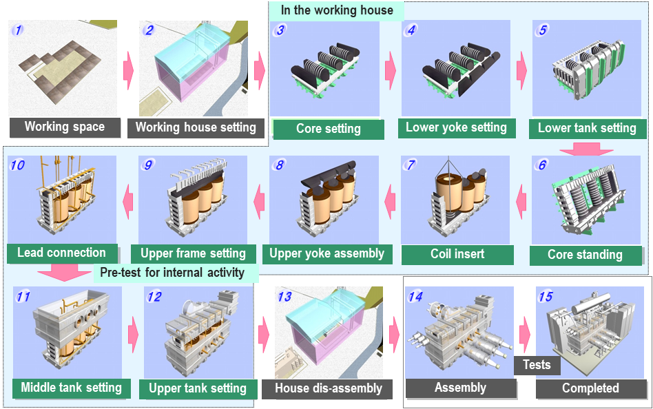
Figure 1 - Example of On-site Assembly Workflow
A survey of site assemblies performed by several manufacturers in Japan, Europe and China presented the following solutions:
- A three-phase five-limb core design is manufactured in four separate “U” cores that can be easily combined at site. The transformer is fully assembled and tested in the factory before being dismantled and shipped to site. The windings are nested together as a single phase for transportation. At site, the “U” cores are assembled onto a bell type tank base and the winding phases are inserted around the core main limbs.
- An alternative three-phase five-limb core design solution was described in which the core legs and yokes are shipped individually to site. A core stacking table is required at site where the bottom yokes are inserted. The core is then lifted upright, the windings are inserted, the top yokes are installed, and the active part assembly is layed in the tank.
- Different solutions for shell form type transformers were also provided.
- A variant of the site assembly was shown to be the split-tank type transformer. The transformer is divided into several tank components that are connected on site such that it will be an equivalent three phase or single phase required rating. For this type, the windings and cores are not assembled on site.
All these solutions have been done on hundreds of transformers globally and ratings above 1500 MVA have been achieved. The field failure rate was shown to be very low.
The survey also reported cases of existing transformers for which new windings were installed at site. Indeed, in the event of failure, it may not be possible or practical to transport a transformer to a factory for repair. This may occur if railways or bridges have been decommissioned and the existing transformer can no longer be transported in the same way it arrived. It is shown to be possible to disassemble the transformer and active part at site, and repair or replace damaged windings. This is designated as “site repair” and involves many similar challenges and solutions as the cases discussed for on-site assembly. The survey included site repairs done in Canada, Japan, China, and Europe. Solutions for the site building / clean house were presented such as special purpose buildings that can be reused and contain the necessary lifting systems or have removable roof panels for mobile cranes. It may be possible to use an existing building at site (i.e. generator hall with high bay ceiling and overhead crane) or a local company can prepare a tent-type building on site. The site building must have a controlled atmosphere for low humidity and minimization of dust.
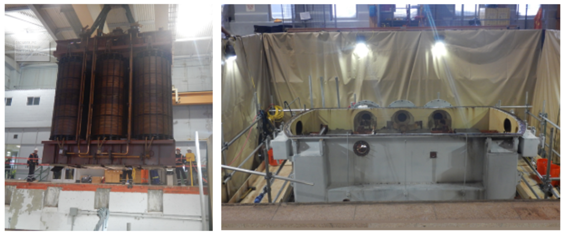
Figure 2 - Core/coils being removed from the tank inside the clean house
Dryout practices of the core & windings were also surveyed. Windings undergo a factory drying by vapor phase method prior to shipment. The various methods to limit moisture ingression during the site assembly process were described. The final dryout at site was reported to be done by either hot oil / vacuum cycles, Low Frequency Heating (LFH) method or vapor phase methods.
The survey showed variations in the final testing of transformers assembled at site. Some manufacturers perform full tests on the assembled transformer in the factory (and some only type test the first transformer) and then only repeat low voltage tests at site. Other manufacturers only do full testing at site on the assembled transformer (no factory testing). All situations were proven to be successful with low field failure rates.
Mobile equipment is available for of all parameter and dielectric verification tests to be performed at site. Loss measurement, impedance measurement, heat run, applied voltage and induce voltage are performed using AC HV test equipment. Lightning impulse voltage and switching surge voltage tests are performed with a mobile HV impulse test set. DC tests such as DC applied, or DC induced voltage tests are also performed with mobile DC test equipment.
Modern mobile AC HV test systems utilize an Electronic Power System (EPS) which can vary the output voltage and output frequency across a wide range during operation. The system includes an inductive and capacitive compensation and a step-up-transformer that can be switched manually into many different configurations. By using external capacitor banks, a heat run test can be also performed at site with this system. Transformers up to 800 kV have been tested with this type of mobile AC HV test system for induced, applied and loss measurement. Heat run testing is limited by available capacitors and the power supply (i.e. typically a very large 2 MW diesel generator). Figure 3 shows an example of HV-AC mobile test system installed in 40 ft container.
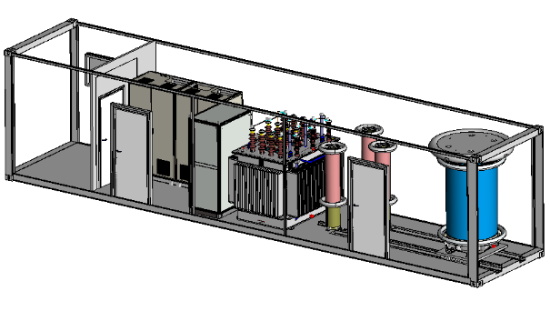
Figure 3 - Example of HV-AC mobile test system installed in a 40 ft container
The HV mobile impulse test set is a modified version of a factory impulse test set where the test circuit lays down flat into a 40-foot ISO container or road trailer for shipment. Mobile impulse sets that can perform testing up to 1800 kV BIL are in use and higher voltages are technically possible.
About the best practices for quality control, a survey of several manufacturers provided detailed quality checks, testing, clean house requirements, processing / dryout and inspection procedures. Table 1 summarizes the major quality assurance items for on-site assembly of transformers.
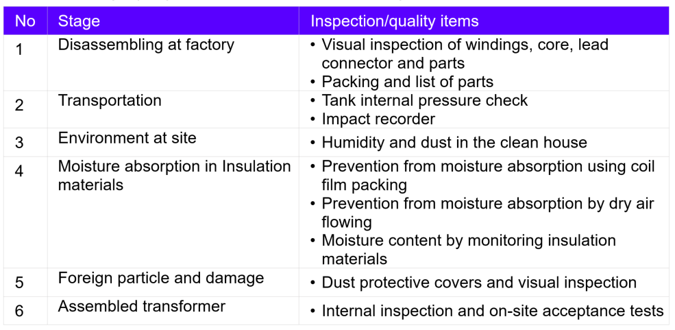
Table 1 - Major quality assurance items for on-site assembly transformers
Conclusion
This Technical Brochure presents a collection of international cases and best practices for the on-site assembly or on-site rebuild of large power transformers. It was overall demonstrated that various solutions have been developed and successfully executed for site assembly and site repair for more than 20 years. The increased risks of performing tasks at site such as windings installation, core assembling, active part drying, and dielectric testing can all be successfully managed. The site assembly and site repair are shown to be viable solutions when required by transport limitations, in accordance with local regulations, practices, and specifications.
Reported field experience with these new methods (in Japan in particular) indicates that good reliability can be expected through high voltage testing at the factory and only low voltage tests at site. For on-site rebuild however, high voltage tests should be generally applied to verify the quality of the work. Finally, this Technical Brochure also provides suitable quality management guidelines for this type of work.

Other Technical Brochures