High-Frequency Transformer And Reactor Models For Network Studies
Transformers are critical components in any power system. The reliable and safe operation of a transformer requires that the stresses imposed by the environment are kept within acceptable limits. Prediction of dielectric stresses from transient overvoltages requires the ability to simulate the overvoltages in the system, e.g. due to lightning strokes, normal switching operations, fault initiation and clearing, and repetitive voltage flanks from power electronic converters. The stresses involve phase-ground voltages at terminals and inside the transformer, longitudinal stresses at the winding end caused by non-linear voltage distribution along the winding, and resonant voltage buildup inside the winding and between external terminals. Adequate models are also needed in general transient studies, where the transformer is just one of many components. The transformer model should preferably be compatible with Electromagnetic Transient (EMT) programs for its use in general studies, in addition to more specialized in-house simulation programs.
Members
Convenor
(NO)
B. GUSTAVSEN
Secretary
(BR)
A. ROCHA
A. PORTILLO (UY), A. HOLDYK (NO), A. PALANI (DE), B. VALECILLOS (CH), B. KORDI (CA), B. ANDRIIENKO (UA), C. GONZÁLEZ-GARCÍA (ES), C. ÁLVAREZ-MARIÑO (ES), D. MATVEEV (RU), D. VUJATOVIC (UK), E. RAHIMPOUR (DE), E. MOMBELLO (AR), E. PORTALES (CA), F. PORTILLO (UY), G.A. DÍAZ FLÓREZ (CO), G.H.C. OLIVEIRA (BR), H. DE HERDT (BE), H.K. HØIDALEN (NO), J.H. KIM (KR), J. VEENS (NL), J.C. MENDES (BR), J.F. LOFRANO (BR), J. MONTANHA (BR), L.F. DE OLIVEIRA (BR), M.O. ROUX (CA), M. OSTRENKO (UA), M. RIOUAL (FR), M. FROLOV (RU), O. STERZ (DE), R. CASTRO LOPES (PT), R. DEGENEFF (US), R. RONCHI (MX), R. AZEVEDO (BR), S. JAMIL (UK), T. RÖHRL (DE), T. NGNEGUEU (FR), X. LOPEZ-FERNANDEZ (ES)
Introduction
A previous Joint Working Group (CIGRE JWG A2/C4.39) concluded in its report (TB 577A, TB 577B) that the existing transformer models have substantial limitations.
- Commonly available EMT programs can only represent the transformer by simple models, typically consisting of a standard 50/60 Hz models where saturation effects may be included, sometimes in combination with lumped capacitances.
- Wide-band transformer terminal (black-box) models can be created based on frequency sweep measurements, but the measurement approach and subsequent model extraction method is far from straightforward. Such models have hardly reached practical use outside academia.
- The transformer manufacturers have themselves available detailed winding models for predicting the internal voltage stresses during the lightning impulse test in factory. These simulation programs are in-house and the applied models are in general not available outside the manufacturer. It was found that different manufacturers got very different voltage wave shapes when applying their computational tools to a common (fictitious) geometry description of a transformer.
Study committees A2 (Transformers) and C4 (System Technical Performance) therefore initiated JWG A2/C4.52 to follow up on the work from JWG A2/C4.39. The main scope of the new JWG was to provide adequate transformer models for use in transient overvoltage studies, including modeling specifications and procedures for including models in EMT programs.
The JWG started its work in 2014 with members from transformer manufacturers, universities, research institutes, and consulting companies. The work was organized in five Task Forces that delivered one TB each. The five TBs are:
- Part A – White-box models
- Part B – Black-box models
- Part C – Grey-box models
- Part D – Model specification and interfacing
- Part E – Measurements and design data
In summary, the JWG has 1) described the most relevant models (Parts A-C) along with guidelines on best practices for parameter determination, 2) provided practical guidelines on model specifications and data formats for inclusion of the models in EMT simulation programs (Part D), and 3) performed measurements on two power transformers for model validation purposes (Part E). The measurements results are made freely available along with the transformer detailed design data on an open web site [1] so that anyone can validate his transformer modeling method.
Part A - White-Box Models
Transformer white-box models are normally proprietary models (software) used by the manufacturers to verify the winding’s ability to withstand the standard voltages used in the factory acceptance tests, i.e., the standard lightning impulse voltage (full and chopped waves) and sometimes also switching impulse waves.
These models can be categorized as lumped parameters circuit models based on a spatial discretization of the windings, or distributed parameters models based on traveling wave-type approaches. The model parameters (self and mutual inductances, capacitances, resistances and conductances) are calculated based on a detailed description of the transformer’s geometry and material properties via formulae and/or finite-element method (FEM) computations. The TB describes the principles and procedures for performing such calculations. Analytical calculations are fast and are generally applied by the manufacturers in the day-to-day transformer design tools. FEM can be used to create models that more accurately reflect the internal construction characteristics of the transformer, and it is in general used by the manufacturers as a development tool. Fig. A1 compares measured and simulated voltage transfer from the HV terminal to the LV terminal (X1), for the 1-ph transformer studied by the JWG. The simulation model is a daily use-type model.
To improve the results obtained by day-to-day manufacturers’ white box models, it is necessary to use more advanced models that take into account the damping variation with frequency. The frequency-dependency of the damping can be approximately taken into account by introducing an empirical damping factor in the lumped parameter model. Fig. A2 shows a comparison between measurement and simulation for the same transformer, when a frequency-dependent damping-factor is used. The damping is more correctly represented, but deviations in the frequency content still exist.
The most promising calculation approach in terms of accuracy is based on the lumped parameters model with the transformer branch impedance matrix calculated as a discrete function of frequency using FEM with the principle of complex permeability, followed by Vector Fitting for state-space model extraction. The resulting model can be included in time-domain simulations programs by a Norton equivalent representing the time-discretized state-space model, or by an equivalent lumped parameter circuit. After the disbanding of the JWG, simulation results by such FEM models have been published [2] which show excellent agreement with measurements in Part E.
Manufacturers may be reluctant to give out detailed models as they may reveal proprietary design information. It may also initiate discussions to the internal validation rules, which are considered manufacturers’ know-how. Therefore, white-box models will normally be passed to their customers in the form of a terminal equivalent only.
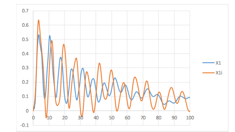
Figure A1 - Transfer of lightning impulse voltage from HV terminal to LV terminal. X1: measurement; X1i: calculation by member "i" of JWG using white-box model for daily use
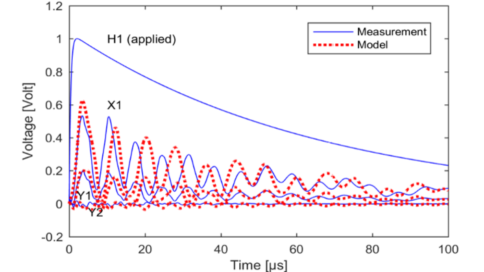
Figure A2 - Transfer of lightning impulse voltage from HV terminal (H1) to LV terminal (X1) and two points in regulating winding. Measurement and simulation when using damping factor method in the model
Part B - Black-Box Models
A black-box model is a terminal equivalent of the transformer. Such model can be used for calculating the overvoltages that occur at its terminals, as well as for use in general system studies. The internal overvoltages cannot be studied, however. The modeling procedure is usually based on frequency domain samples that represent the terminal admittance matrix. The frequency samples can be calculated from the white-box model (in which case the accuracy of the black-box model is limited by that of the white-box model), or be obtained by measurements. In the latter case, a very accurate terminal characterization can often be achieved. Most works describe measurements by dedicated setups that allow to measure the admittance elements one-by-one. Other works are based on standard sweep frequency response analysis (SFRA) measurements or modal-domain measurements. In any case, the modeling becomes more difficult in the case of non-grounded windings and when many external terminals must be considered. Careful calibration procedures must always be applied. It is also possible to include tap changer contact points in the model by use of voltage transfer measurements, provided that such points are available for measurements.
The input data are fitted with a multi-terminal high-order rational model, e.g. in the pole-residue or state-space form. The model extraction process normally includes the calculation of an initial model (e.g. using Vector Fitting), followed by a passivity enforcement step (e.g. residue perturbation) to ensure stable behavior in the time-domain simulations. The model extraction part can be done with acceptable accuracy and within acceptable computation times.
The successful development and use of black-box models has been demonstrated in the literature for a wide range of transformers, from distribution transformers to power transformers and HVDC transformers, often giving good results up to 1 MHz and even beyond. Excellent results were also obtained by the JWG for the two transformers described in Part E. Currently, the successful creation of accurate models requires a specific expertise, in particular for the measurement part. The same measurement and modeling procedure is also applicable to shunt reactors.
Fig. B1 shows measured admittance data and the behavior of a high-frequency model that was fitted to the data of the 1-ph 3-winding transformer that was subjected to measurements by the JWG. The accuracy in time domain simulations is very good as demonstrated in Fig. B2.
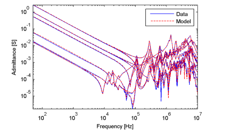
Figure B1 - Measured admittance data and model behavior for 1-ph transformer
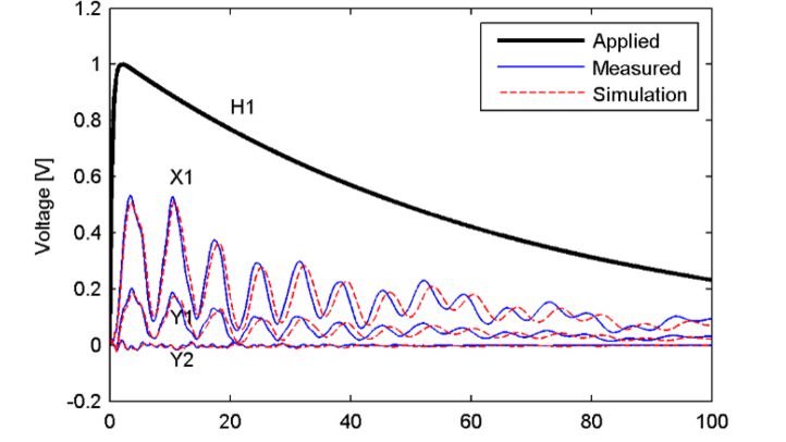
Figure B2 - Validation of the model's accuracy in the time domain
Part C - Grey-Box Models
Grey-box modeling of transformers is a compromise between black-box modeling based on measurements and white-box models based on design information. This can both be simple lumped parameter models and sophisticated ladder networks. The former is based on limited and typically available data; these are (with exception of M2) also applicable for low-frequencies transients and are easily initialized. The latter requires sophisticated fitting of many electrical parameters or geometrical data.
Simple topologies
The simple topologies consist, in general, of low frequency (LF) transformer models extended with shunt and series capacitances at the terminals. The TB Part C provides information on typical values and calculations based on test-report and frequency response measurements. Figs. C1-C4 show the four models analyzed in this text.

Figure C1 - M2 - Artificial RLC-equivalent
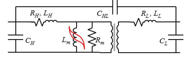
Figure C2 - M3 - Simple LF-equivalent with concentrated shunt capacitances
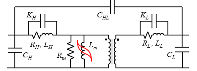
Figure C3 - M4 - Simple LF-equivalent with concentrated shunt and series capacitances
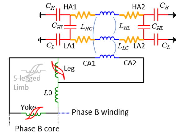
Figure C4 - M5 - Three-phase model with capacitances concentrated on each side of the winding, shown for phase A
Ladder network topology
The ladder network topology consists of an arbitrary number of sections with series impedance and shunt admittance, including mutual coupling to other sections, as shown in Fig. C.5. Such model is only valid for frequencies above 10 kHz since the nonlinear behavior at low frequencies is ignored. The nature of the grey-box approach is that there is only limited information available about the design, so the number of sections is arbitrary, and sections are also assumed to be equal to a large extent. Analytical formulae, similar to the white-box approach, can be used to calculate initial values of the parameters that later are fitted to terminal measurements. Information about the type of winding (layer, disc etc.) can be used to establish better initial values. The fitting can be based on the direct fitting of series and shunt elements, or indirectly of geometrical parameters which requires physical formulation of relation between geometry and electrical parameters.

Figure C.5 - Ladder network topology
Test case
The transformers T1 and T2 documented in the TB part E) are used to illustrate the accuracy of fitting primarily for the simple topologies. Fig. C.6 shows the agreement between the measured frequency domain admittance seen into the primary (115 kV) with the secondary (34.5 kV) short-circuited. Only M4 can reproduce the dual peak around the first resonance (50 kHz), but the determination of the series capacitance in this model is uncertain without the measured frequency response at hand. Crucial for the good agreement is the addition of an extra damping resistance.
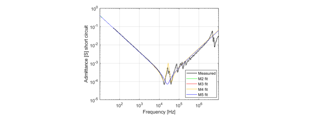
Figure C.6 - Fitting of the T1 short-circuit response of T1
Even if the frequency response shows a reasonable agreement, the time domain response could be different. Transient recovery voltage calculation as shown in Fig. C.7 is used to demonstrate the simple model accuracies as this requires high model accuracy around the dominant resonance frequency.

Figure C.7 - System for calculation of transient recovery voltage in a transformer through-fault case
Fig. C.8 shows the calculated TRV for the four models M2-M5 that have been fitted to the measurements. In addition is shown a reference result by a high-order black-box model (BB), derived from the frequency domain measurement using Vector Fitting. Compared to the BB result, the M4 model manages to capture the oscillations of the TRV while the other models give a response with too steep front and too high frequency of the oscillation.

Figure C.8 - Result and comparison of TRV calculation with fitted models
Part D - Model Interfacing and Specifications
Interfacing
The models involved can be complex and involve a large number of data, in particular for the white-box and black-box models. As no universally accepted model data formats are available, the transfer of model data between parties could be difficult, e.g. a manufacturer would like to provide models to their customers, but they could be using a different EMT programs.
The JWG has therefore proposed that the model data are transferred in the form of ASCII text files with a predefined format. It is then up to the EMT program developers to make their programs able to read the information from the text files. Model data formats are proposed for the most common model formulations, along with simple pseudo codes for writing/reading the data to/from the file. Simple examples are also provided.
In some situations, it could be that the transformer information is to be transferred in the form of frequency domain data samples, e.g. measured admittance data, or samples calculated from a white-box model. Data formats are also proposed for such situation.
Specifications
It is advantageous that the model or model input data are acquired at the time of transformer purchase. The TB provides guidelines on what model requirements are needed for what kind of applications, and it proposes requirement statements in terms of model types and applications. The specification should be formulated in collaboration with the manufacturer.
Customer-transformer stepwise actions
A model could also be used during the initial purchasing stage to assess the probable overvoltages that can occur in the transformer and/or the adjacent system. As the design has not yet been fixed, it could be useful to first provide a very simple model, e.g. a lumped parameter model as in Fig. D.1 for the assessment of steep front overvoltages. These terminal voltages could also be used by the manufacturer to ensure that the transformer will be able to withstand the occurring overvoltages. A more detailed model of the finalized model could be provided afterwards, if needed.
Figure D.1 - VFT simplified model for very fast transient analysis
Part E - Measurements and Design Specifications
Open data source
A transformer manufacturer [3] kindly allowed the JWG to perform measurements on two core-type three-winding power transformers, a 1-ph unit and a 3-ph unit. In addition, it shared the design details of the transformers. Together, this information (measurements plus design data) allows the validation of transformer modeling methods, and the information was extensively utilized by the JWG in Parts A-C. Moreover, the data has been placed on an open WEB site [1] for use by anyone.
Measurements
The measurements were performed without oil and without lid and bushings, see Fig. E.1. The following quantities were measured in the frequency domain, for alternative tap settings.
- Voltage transfer between external terminals.
- Voltage transfer from external terminals to three points in the regulating winding.
- Terminal admittance matrix.
The voltage transfer data were fitted with a high-order, rational function, thereby permitting the time domain voltage response to be calculated for any voltage excitation, by use of recursive convolution. The procedure was used to generate the responses of the standard 1.2/50 µs lightning impulse. One such example is shown in Fig. E.2.
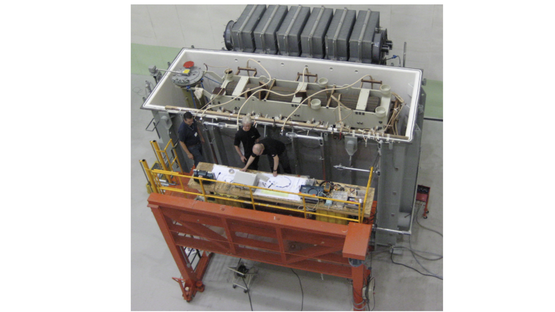
Figure E.1 - Measurements on a 3-ph transformer by JWG
Figure E.2 - Example of time domain lightning impulse responses
Design data
The principal design data of the two transformers are as follows:
- Single-phase transformer
50/50/16.67 MVA ONAF.
230/Ö3 / 69/Ö3 / 13.8 kV, 60 Hz.
±10×1% OLTC at HV Winding
Core – 1 Wound Leg with 2 Return Legs Core-Type
Tertiary winding – Helical with CTC conductor
LV winding – Continuous disk with CTC conductor
HV winding – Interleaved disk with rectangular conductor
RW winding – Interleaved disk, with rectangular conductor
- Three-phase transformer
92/92/30.67 MVA, ONAF.
115/34.5/13.8 kV, Ynyn0d1, 60 Hz
The transformer is of variable induction
OLTC is in the HV winding to regulate LV voltage
Core – Three-legs Core-type
Tertiary winding – Helical with CTC conductor, with series reactor to limit short-circuit currents.
LV winding – Helical with CTC conductor
HV winding – Continuous disk with CTC conductor
RW winding – Multi-star, with rectangular conductor
For further information on the design details, it is referred to the brochure Part E and/or the dedicated web site.
Recommendations
General
- Manufacturers should start offering models to their customers.
- Depending on the intended application, the model asked for could range from a simple model consisting of a standard 50/60 Hz model in combination with suitable capacitors, to a frequency-dependent black box model, and even a detailed white-box model.
White-box models
- The manufacturers should improve their models with the objective to not only obtain good approximations for the maximum values of internal voltages, but also to obtain better wave shapes. This implies that they should improve their methods used for calculating inductances and capacitances that represent the transformer, with inclusion of frequency dependency.
- To extend the lumped parameter model for use at higher frequencies, like VFTO (Very Fast Transient Overvoltages), it is necessary to divide the windings turn by turn. It may also be necessary to include detailed models of leads, bushings, tank walls, and shields.
- The modelling of frequency dependent damping effects is fundamental to obtain good results in time and frequency domain.
- The creation of more accurate models can be time consuming and costly for the manufacturers, and at the same time the current experience is that customers tend to ask for better models with little willingness to pay for the additional work. This situation can prevent widespread use of more accurate white-box models.
Black-box models
- Black-box models from measurements should be used when high accuracy is needed over a wide frequency band.
- The suppliers of SFRA measurement equipment should adapt their product line in the direction of modeling (in addition to diagnostic fingerprinting).
- Proper guidelines should be provided in terms of measurement setups and usage, model extraction, and model validation.
Grey-box models
- These models are the only option in the planning stage as no data is then available for detailed white-box or black-modeling. Grey-box models are also useful options in high frequency studies as they do not require deep knowledge of the transformer design, and they are easy to apply.
- Simplified models can represent the behaviour up to the first resonance frequency point. The often-complex behaviour around and after the first resonance frequency is not well represented by the simplified models (M1-M5).
- Capacitance values obtained from dielectric tests must be reduced when used in high-frequency transient studies. A scaling factor in the range of 0.4 to 0.6 is recommended. An additional scaling may also be needed to deal with the winding connections.
- The model's damping can be represented by a shunt resistance that is calculated based on a typical damping factor, the terminal leakage inductance, and the effective capacitance. The transformer models M3-M5 based on test report data only will have too small damping.
- The use of an detailed, fitted ladder network described is still an area of research and needs more exploration before a conclusion can be made.
Model interfacing and specifications
- The provided information in Part D could be useful when requesting models.
- The transfer of models should be done using text files, e.g., by the formats proposed in Part D. The developers of EMT simulation programs should be able to read from these data files and implement the associated models.
Measurements and design specifications
- Manufacturers should make use of the results from the JWG to validate their models, e.g., by creating a model of the 1-ph and 3-ph transformer from the provided design data, and compare against the provided measurement results.
References
- www.sintef.no/CIGREtransformerdata
- E.E. Mombello, Á. Portillo and G.A.D. Flórez, "New state-space white-box transformer model for the calculation of electromagnetic transients," IEEE Trans. Power Delivery, vol. 36, no. 5, pp. 2615-2624, Oct. 2021.
- WEG Equipamentos Elétricos S.A. (www.weg.net)

Other Technical Brochures