Protection for Developing Network with Limited Fault Current Capability of Generation
Protection is important to safe and reliable operation of the power grid. Traditional protections are designed based on the fault characteristics of the conventional system with thermal power as the main energy sources. However, new generations, network structures and loads are integrated into the grid, which leads to challenges for protection functions.
Members
Convenor
(CN)
T. BI
Secretary
(CN)
K. JIA
S. RAJNISH (AU), G. PHILIPPE (BE), V. FRANCO (ZA), P. NAGARAJU (UK), R. ATHULA (CA), B. CHRISTIAN (DE), N. PHILIP (UK), S. SACHIN (IN), X. XIONG (CN), W. BJORN (SE), H. FAHD (UK), M. GHEORGHE (RO), N. NIRMAL (NZ), M. SURESH (IN), C. ROBERTO (ES), S. MICHAEL (US)
Introduction
High proportion of power electronic devices are penetrating the power sources, power grid and load of the power system. Due to the depletion of fossil energy and increasing environmental pollution, renewable energy represented by wind power and photovoltaic power is gaining more and more attention all over the world. These new power sources, whose generation mechanism is different from that of synchronous generators, are changing the fault characteristics of the system. In addition, new structures, such as active distribution network, microgrid and VSC-HVDC, are widely applied to improve energy efficiency, popularize and promote the use of renewable energy. These changes results degradation of traditional protections, and even the risk of maloperation and rejection.
Models for fault current calculation is the basis of analyzing system fault characteristics, researching protection adaptability and putting forward new protection principles. According to the industrial projects, this brochure provides different testing system benchmarks for protection research. To establish the short-circuit current model of various power electronic devices in different scenarios, we must start with the control system and get the fault current characteristics by combining the typical topology and parameters derived from industry application. Based on this, the subsequent analysis of protection adaptability and exploration of new protection principles are carried out.
Based on the analysis of fault characteristics, this Technical Brochure researches the performance of traditional protection in order to determine the protection configuration principles and explore new protection principles. The researched protections include the traditional protection principles based on current, impedance, communication, traveling wave and islanding protection.
To solve the problems faced by conventional protection, it is particularly important to research the new principle of relay protection adapting to the limited fault current sources. This Technical Brochure presents the novel protection principles of renewable energy power plants, AC/DC hybrid system, and DC distribution system. The new protection principle proposed at present can adapt to the integration of limited fault current power supply to a certain extent. However, most of these protection principles are in the theoretical research stage and have not yet been applied to industry engineering. The results of the survey conducted by this working group are presented at the end of the document. And it is recommended to do more systematic researches for protection of the developing network.
Structure of the Technical Brochure
The Technical Brochure includes the following chapters:
- §1 introduces the current status and future requirements of renewable energy, power grids and electrical vehicles of various countries, including China, the United States, Europe, Canada, and India.
- §2 presents the topology and characteristics of wind generation, photovoltaic power generation, energy storage and electric vehicles.
- §3 presents structure changes of the power grid with high proportion of power electronic devices. The chapter also includes topology analysis and fault analysis of various new structers, including active distribution network, microgrid and VSC-HVDC.
- §4 provides models of different renewable energy sources for fault current calculation, as the basis of analyzing system fault characteristics, researching protection adaptability and putting forward new protection principles.
- §5 presents the analysis of impacts of wide application of power electronic components on individual protection.
- §6 presents novel protection principles of renewable energy power plants, AC/DC hybrid system, and DC distribution system.
- §7 provides the conclusion including recommendations to improve protection for developing network.
Testing System Benchmarks for Protection Research
According to the existing engineering projects, the networks integrated with various power electronic devices can be categorized as 4 scenarios. In this brochure, we have set the different testing system benchmarks for different relay operating situations for our members as follows.
Scenario 1: AC/DC Hybrid Distribution System
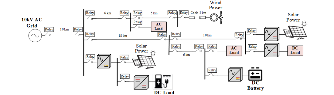
Figure 1 - Diagram of AC/DC hybrid distribution system
AC/DC Hybrid Distribution System contains AC grids, renewable power generations, industrial AC loads, DC batteries and DC loads, DC data centers and low voltage residents' living loads.
Scenario 2: Large Scale Wind/PV Generation and Integration System
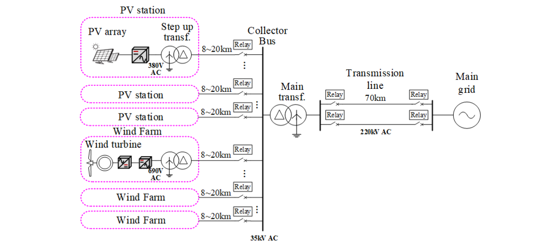
Figure 2 - Diagram of large scale wind/PV generation and integration system
Large scale wind/PV power generation and integration system has the low voltage level of power collection lines, step up transformers, main transformers and transmission lines.
Scenario 3: Multi-Terminal High Voltage VSC-HVDC System
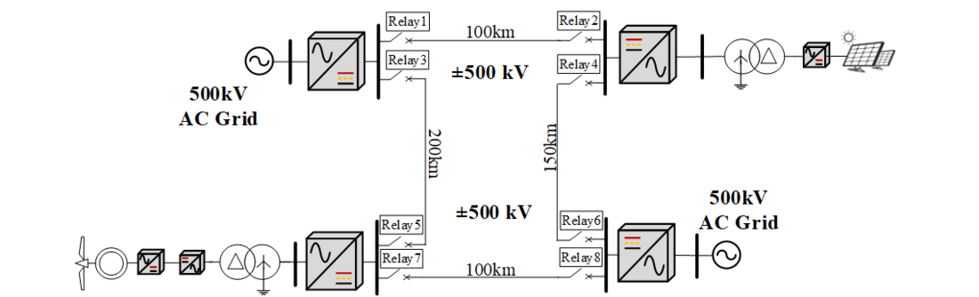
Figure 3 - Diagram of multi-terminal high voltage VSC-HVDC system
Multi-terminal high voltage VSC-HVDC system contains DC breakers, lines and at least three VSC-HVDC power conversion stations which can connect to both AC renewable generation systems and the AC grids.
Scenario 4: High Voltage LCC-HVDC Transmission System
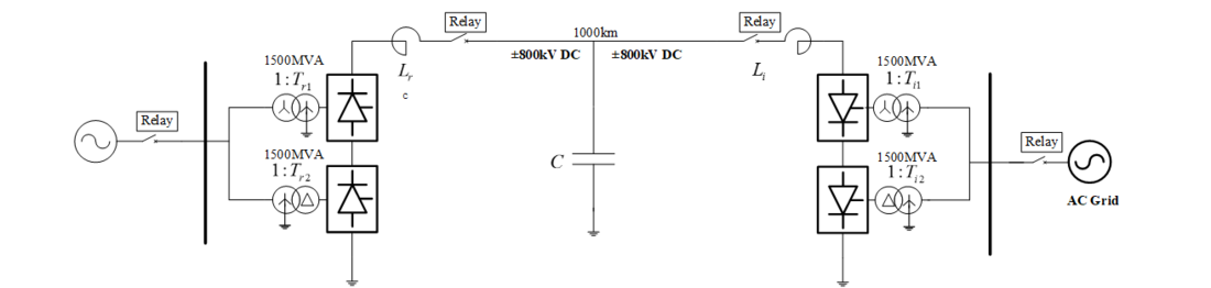
Figure 4 - Diagram of high voltage LCC-HVDC transmission system
High voltage LCC-HVDC transmission system has LCC-HVDC power conversion stations, DC lines, DC Breakers and AC lines and its breakers.
Models for Fault Current Calculation
Naturally, as the penetration of inverter-based resources continues to increase on the bulk power system (BPS) and sub-transmission system, the levels of fault current and short circuit strength will continue to drop. Low fault current and low short circuit strength conditions pose a number of challenges to BPS reliability. In order to research the impact of high proportion power electronic equipment on fault protection system, fault current model of the inverter has to be studied.
Type-III Wind Farms
The control structure of the doubly-fed induction generator is shown in Figure 5. The rotor-side, grid-side converter and crowbar protection are used to achieve DFIG operation control under different operating conditions. The rotor-side protection circuit contains an active crowbar protection with a three-phase AC switch and a bypass resistor. Figure 5 shows the topology of the crowbar circuit and the corresponding input and removal control methods. When the power grid is disturbed, the DFIG rotor current peaks Exceeding a predetermined threshold, the crowbar resistance is turned on; and when the unit terminal voltage and the stator rotor current return to normal, the crowbar resistance is cut off, and the rotor converter performs normal power adjustment. For the three-phase stationary coordinates, the stator voltage and current can be obtained in time domain as:
(1)
where, U, I and φ are the RMS values and phases of stator voltage and current, superscripts + and - represent positive and negative sequence components, subscripts u and i represent voltage and current phases, and ω is synchronous electrical angular velocity.
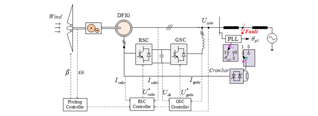
Figure 5 - Structure diagram of a DFIG system
The approximate angular velocity and magnitude of current components, or the fault current when stator is superconductive, can be expressed as:
(2)
where Lop and L'op are defined as steady-state and transient inductances, while E and E' are defined as steady-state and transient excitation voltage of Type-3 WT, respectively.
Inverter-Interfaced Power Plants
According to the analysis of the inverter mathematical model, the control principle diagram of the IIDG inverter shown in Figure 6 is obtained.
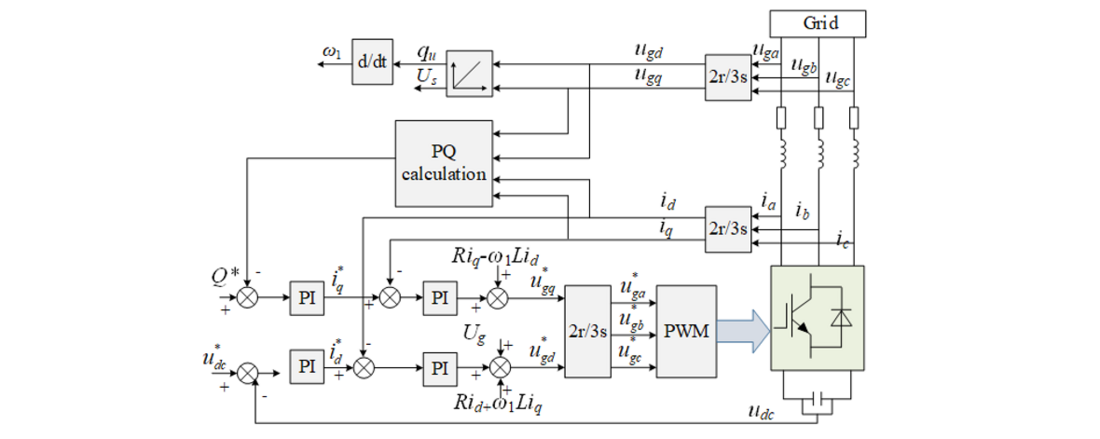
Figure 6 - Control diagram of IIDG inverter
When the positive-sequence voltage of the grid-connecting point drops below 90%, the outer loop of the power voltage is disconnected, and the active current command and reactive current command are given directly in the inner current loop. According to German grid standards for access to medium-voltage grid-connected distributed power, during the grid fault, the reactive current command is adaptively adjusted according to the voltage drop range, that is:
(3)
where all quantities are p.u. values. α is the positive sequence voltage amplitude of the power.
The approximate expression of IIDG inverter can be given as
(4)
where, time constant τacc is the decay time constant, ωacc is the natural frequency.
Performance of Protection Scheme
New protection principles based on current, impedance, communication are presented in the technical brochure to ensure safe and efficient operation of power system. Hereinto, the current waveform similarity based pilot protection is selected as a representative.
The typical primary system with integrated wind farms is shown in Figure 7. CTw and CTs are the current transformers on the wind generation (W) side and system (S) side respectively, and the positive direction of the current is from the bus to the transmission line.

Figure 7 - Diagram of the primary system of an integrated renewable energy power plant
The criterion for the protection based on cosine similarity is as follows:
(5)
where the subscript ϕ is phase A, B or C. cosset is the protection constant of the proposed protection, which is related to CT saturation and CT error. Detailed pickup setting refers to the brochure.
The performance comparison between the ratio differential protection and the cosine similarity longitudinal protection under the scenario of renewable energy station connected to weak system is given below. In the case of renewable energy station accessing weak system (the capacity ratio of renewable energy station to synchronous system is 1:4), the current differential protection has the possibility of rejection when the phase to phase fault occurs on the outgoing line. And the reason is that the distortion of the short-circuit current provided by the renewable energy source leads to the situation that the phase angle between the fault phase short-circuit current on both sides is greater than 90 degrees, thus the differential current is less than the restraining current.
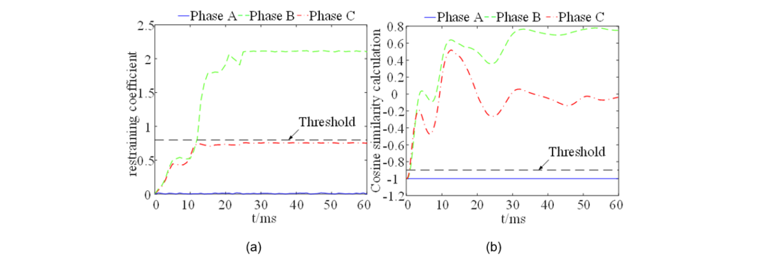
Figure 8 - Performance comparison between conventional pilot protection and protection based on cosine similarity. (a) Performance of differential protection; (b) Performance of the proposed protection
Test results show that the protection criterion based on cosine similarity can solve problems of sensitivity reduction and incorrect operation of conventional protection due to the integration of large-scale renewable energy power plants.
Conclusion and Recommendations
Protection is vital to the safe and efficient operation of the power system. High proportion of power electronic devices throughout the power grid results performance degradation of traditional protections. Based on analysis of the fault characteristics of various power electronic devices, new protection principles have been proposed, adapting to the integration of limited fault current power supply to a certain extent. However, most of these protection principles are in the theoretical research stage and have not yet been applied to industry engineering. In order to promote the practical process of the new protection principle, more systematic researches are needed.

Other Technical Brochures