Recommendations for the use and testing of Fibre Optic Cables used in Land Cable Systems
Fibre Optic Cables (FOC) are used in power cable systems for communication purposes but also for monitoring. Depending on the variable to be monitored and/or the system configuration FOC can be integrated in the power cable.
Members
Convenor
(ES)
A. BURGOS
G. BARNEWALL (AU), D. LIEMANS (BE), D. KHOMARLOU (CA), T. SCHEHADE (CA), S. EBERHART (CH), Y. ZHAO (CN), H. OTTERSBERG (DE), E. CASTILLO (ES), S. KWIK ALLAN (ES), F. CHARLES (FR), N. LOUDIERE (FR), J. WAN (GB), P. MAIOLI (IT), T. KOLTUNOWICZ (NL), G. SANDE (NO), P. HOLMBERG (SE), J. HERMAN (US), J. KWITSCHAU (US)
Background
By 2017 some cable failures occurred in submarine cables with integrated FOC, so a task force (TF B1.70) was created to discuss whether or not to establish a new Working Group. During the work of the task force, the group concluded that the Working Group should be split into two Working Groups – one dealing with submarine cables and the other dealing with land (underground) cables. Two Working Groups were created:
- WG B1.70: Recommendations for the use and the testing of optical fibres in submarine cable systems, approved in March 2019
- WG B1.73: Recommendations for the use and testing of Fibre Optic Cables used in Land Cable systems, approved in November 2019
Introduction
Traditionally, FOC were used in power cable systems exclusively for communication purposes. Technology advancements now allow fibre optics to be used to detect several aspects of the power cable's operating condition. The need to increase the availability and to optimize the operation of the power cable has made having knowledge of the cable's operating condition an important aspect. Cable monitoring provides an awareness of the status of the cable and can be used to detect, locate or even predict future failures. Optical techniques have proven to be a very good way of monitoring. Nowadays, fibre optics can be used to detect temperature, strain and vibration. Fault detection and its location is also an important issue in underground power cable systems, often leading to high costs and long repairing times.
When the only reason for the installation of FOC is communication, these cables are located independently of the power cable, so that any problem or need for maintenance in one of them does not affect the other. In the case of monitoring systems, the closer the sensor is to the element to be monitored, the more accurate it is. This drives cable and system designers to require the FOC to be incorporated within the power cable itself.
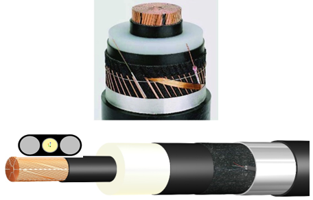
Examples of underground cables with embedded FOC
The act of including FOC in the power cables implies modifications to the tests to be carried out, and additional considerations to be taken into account in the power cable system design and installation (configuration, earthing, etc.)
External FOC have been installed alongside power cables for many years so the characteristics, design considerations, testing, installation and commissioning are well established in various standards and guides. Embedding the FOC in the power cable is more recent. This Technical Brochure collects the standards and recommendation already available for the use and testing of fibre optic cables used in underground systems and includes recommendations on points not totally covered by them.
This TB is focused on underground power cables, while the TB written by the WG B1.70 will cover submarine power cables.
Technical Brochure scope and structure
The TB covers the following aspects:
- Technology of the optical fibres, fibre optic cables and their accessories.
- Design, including the different possibilities depending on the sensing applications, the location of the fibre, the optical fibre protection, the excess length management, the earthing of the system (including induced voltage considerations) and the accessories design.
- Testing, including type tests, factory quality control tests, and commissioning tests.
- Recommendations in operation and maintenance.
The TB covers both AC and DC underground systems. Submarine cables and the transitions from submarine to underground systems are being covered by the TB of WG B1.70. Although different insulation technologies may be used (XLPE, EPR, paper/mass impregnated), this TB only covers the most common insulation used for underground cable systems (XLPE).
The structure of the document is as follows:
- Chapter 1 Includes the background and scope of the Technical Brochure.
- Chapter 2 Gives an overview on the technology available on the market. It describes some of the aspects of fibre optic technology which are relevant to underground cables and outlines the types of fibre optic cables available. It also includes a description of the accessories, both for external and embedded options.
- Chapter 3 Describes the design considerations for external and embedded fibre optic cables. It includes optical, electrical and mechanical considerations from different perspectives: the use of the FOC, the type of installation, the characteristics of the power system, etc. A comparison between external and embedded FOC is provided as a guide. For both options this section describes the cable construction, the location of the FOC, the accessory designs and the grounding system requirements. It touches on important aspects such as redundancy, maintainability, induced voltages and recommendations on bonding systems.
- Chapter 4 Covers the product testing (type tests and factory quality control tests) on the external and embedded FOC. For external FOC there are standards that cover these tests. In the case of embedded FOC there are additional tests that the FOC will be subjected to as an inherent part of the power cable. For both cases, references to the standards are included.
- Chapter 5 Covers the installation and commissioning aspects. The laying of external FOC can be carried out according to the same principles as the laying of power cables. Power cables with embedded FOC can be more sensitive to mechanical stresses than cables without embedded FOC and consequently must be handled more carefully during cable installation, jointing, and termination work. This section includes the tests and/or measurements to be performed during and after installation.
- Chapter 6 Includes operation and maintenance aspects.
- Appendices: Appendix A includes abbreviations and symbols. Appendix B includes a list of standards and other references. Appendix C includes details about the fibre tests (referenced in Chapters 4 and 5).
Conclusion
This new Technical Brochure provides a general guide, using the current state of the art in technology, for the use and testing of FOC in underground cables. It includes design, tests, installation, commissioning, operation and maintenance aspects, for both external and embedded options, although its focus is mainly centered on embedded fibres. It collects the available standards and provides recommendations on points not totally covered by them. Advances in technologies and specific needs from the particular monitoring systems require that the final users and manufacturers (both for cables and for monitoring systems) analyze the best solution in the design stage, taking into account the whole life cycle of the systems.

Other Technical Brochures