Compact AC overhead lines
With the limitations on obtaining right of way as well as the need for increased power flow in existing corridors, one option that can be employed is to compact the line. This provides for narrower right of way and increased power flow capability. This brochure covers the theory the engineer needs to consider for compacting of AC lines as well as calculated examples. Case studies from around the world are provided relating to compacting of lines as well as voltage upgrading. Live line maintenance and construction issues are also addressed as well as mechanical issues such as sub-span oscillation and galloping mitigation.
Members
Convenor
(ZA)
R. STEPHEN
Secretary
(US)
B. FIFE
D. DOUGLASS (US), L. NAZIMEK (PL), J. FERNANDES (BR), J. NOLASCO (BR), Y. HACHIZAWA (JP), O. REGIS (BR), P. HERRIAS (ES), K. REICH (AT), J. IGLESIAS (ES), S. STEEVENS (DE), J. JARDINI (BR), H. VALENTE (PT), W. KIEWITT (DE), C. WANG (CA), W. LEE (KR), G. WATT (CA), D. LIEBHABER (US), C. WINTER (DE), D. LOUDON (NO), Y. YAMANAKA (JP), E. MARSHALL (ZA), M.SOUZA (BR), C. NASCIMENTO (BR)
Reviewers : W. TROPPAUER (AT), K. HALSAN (NO), H. LUGSCHITZ (AT)
Introduction
The increased urbanisation and demand for power in built up areas has led to increased power requirement in limited corridors. This has led to the need for more compact lines where the same power can be transferred in a narrower right of way.
This brochure covers the compact design of AC overhead lines. There is another brochure under development at the time of writing covering DC overhead lines.
It is often not possible to rebuild old infrastructure to increase the power flow in a corridor. Uprating of the existing line will require either new conductors or a voltage upgrade requiring increased voltage gradients on the same tower with insulators and clearances. This is, in effect, a compact line, as the voltage stress is increased beyond the normal stress levels on more conventional lines.
Another requirement for increased voltage stress or compactness, is the reduced impedance levels which are prevalent with decreased phase spacing, increased number of sub-conductor bundles or expanded bundle designs. This reduced line impedance allows for an increased power flow down the line. These techniques can be used to match the impedance and hence power flow in corridors or it can increase the power flow without series compensation in longer lines.
This brochure explains the concept of compaction for reduced right-of-way as well as increased power flow. Increased power flow can be realised by bundle expansion and phase compaction or by increase line voltage. All result in increased electric fields and other effects which are necessary to manage in the design of a compact line.
Scope
The scope of this brochure is limited to AC overhead lines. The concept of compactness is expanded to include effects of increasing voltage as the effects and considerations for line design are very similar to that of compacting phases. The brochure covers the theory that needs to be understood by the engineer as well as case studies from around the world.
Description of the Brochure
The brochure covers the following aspects:
- Introduction to electrical parameters of an AC overhead line (OHL) – this covers the calculation of the surge impedance loading which is dependent on the resistance, impedance and capacitance of the line.
- The AC resistance is fairly complicated and reference is made to relevant CIGRE brochures. A summary of the parameters involved is covered in this brochure.
- The inductance and capacitance are also explained. In summary in order for a high surge impedance loading it is desirable to reduce the inductance and increase the line capacitance. This can be achieved by reducing phase spacing, increasing bundle diameter and increasing the number of sub-conductors in the bundle.
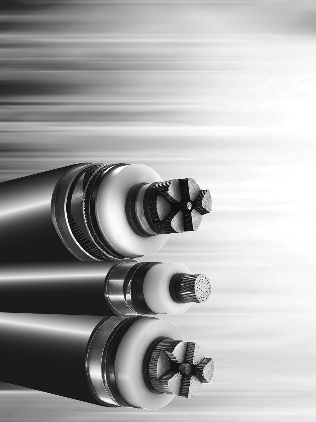
- The reduction of phase spacing increases the surface gradient of the conductors in the bundle which increases the risk of exceeding audible noise limits (Figure1). The aspect of corona and audible noise is covered in the brochure with reference to relevant brochures on the subject.
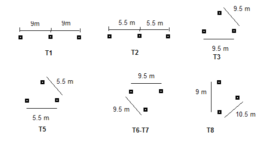
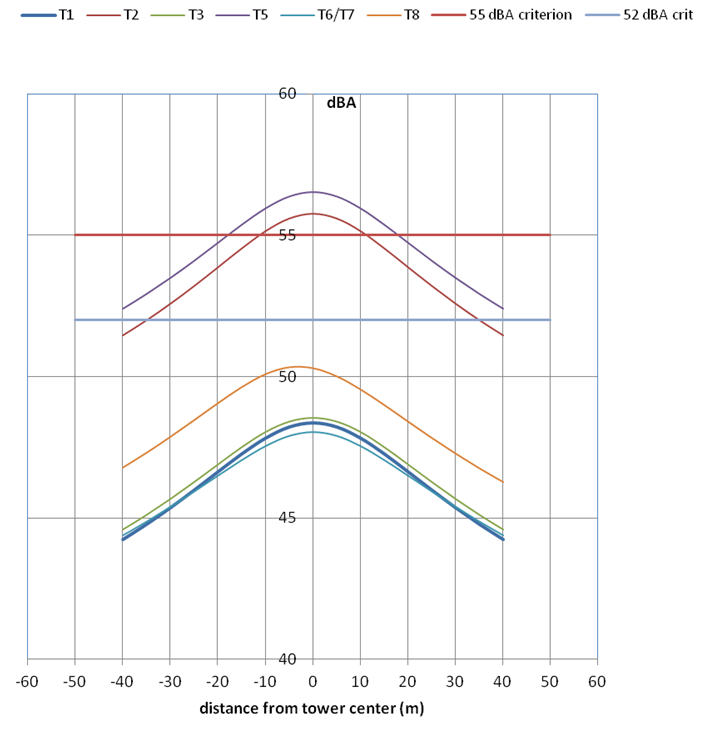
Figure 1 - Audible noise as a function of phase configuration 550kv
The above sections covered in chapters 1 to 3 provide an overview for the engineer on the calculation of line parameters and how these parameters can be altered by the phase configuration and bundle design. The constraint of corona is also covered providing the engineer with the ability to design within constraints.
When the line is compacted the clearance between phases as well as the tower is also reduced. This reduces the lines ability to withstand surges. The source of the surges can be either lightning or switching induced. The section on insulation co-ordination covers the basic theory of insulation co-ordination as well as the influence of atmospheric conditions on the flashover withstand of the gap. Calculation examples are provided to enable the engineer to better understand the concept. The calculation and effect of conductor swing is also covered.
The mechanical design, discussed in chapter 4, covers aspects of the line which includes wind and ice loading. Hardware and tower designs are then described with a number of tower options presented for the engineer. These are later used to describe the calculation of the electrical parameters for each option. This allows the engineer to understand the effect of the different designs on the line parameters and constraints.
Chapter 5 discusses live line maintenance techniques for compact lines where the gaps are reduced. Techniques such as gapped devices and moving the conductor to increase the gap are described Figures 2 & 3).
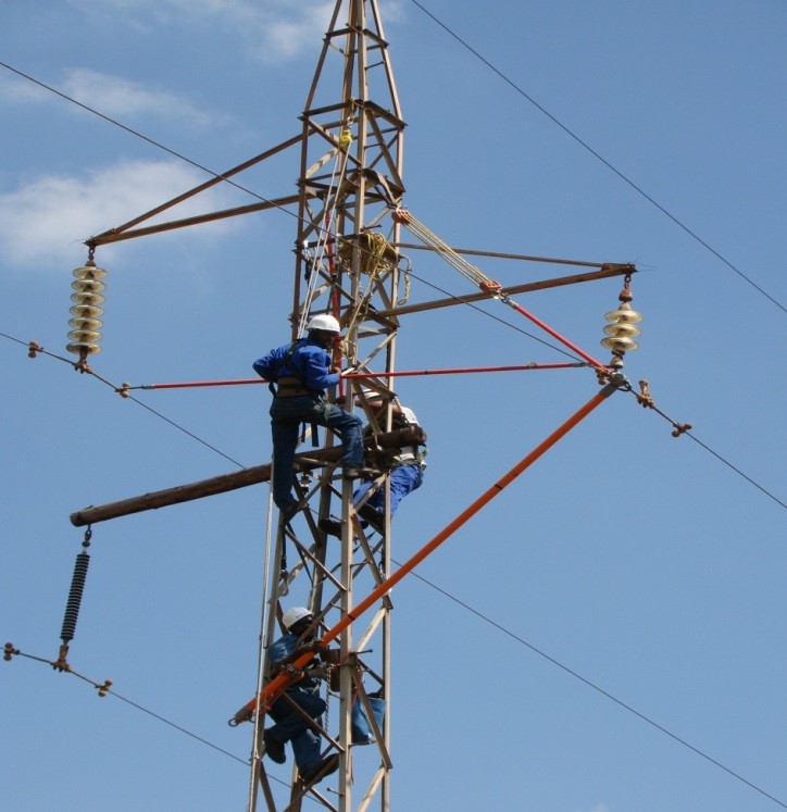
Figure 2 - Live line stick techniques
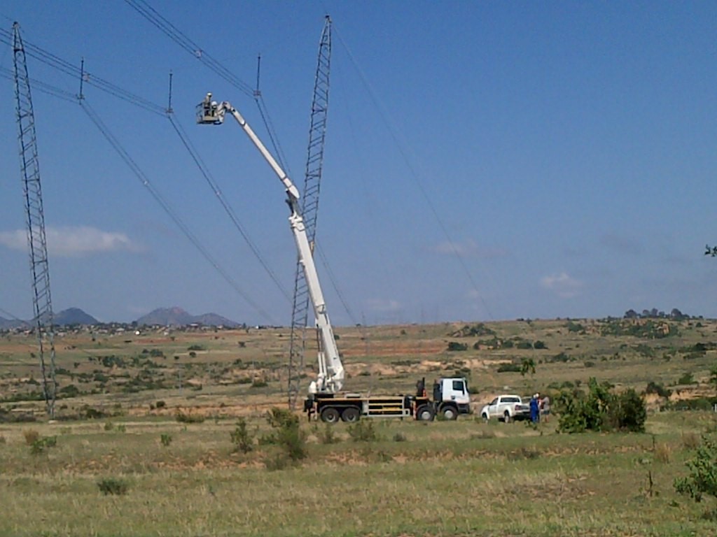
Figure 3 - Live working on cross rope tower
Construction of compact lines is covered in chapter 6. Techniques are not dissimilar to conventional lines.
Chapter 7 calculates the different parameters for each of the tower configurations mentioned previously. This provides the engineer with a visual view of the effect of the tower configuration on the various parameters including the electrical and magnetic fields.
Chapter 8 contains ten case studies from around the globe where different solutions have been designed and implemented for narrow right of way and increased power flow requirements. The engineer can view and understand the different options available to them that have been developed and implemented (Figures 4 & 5).
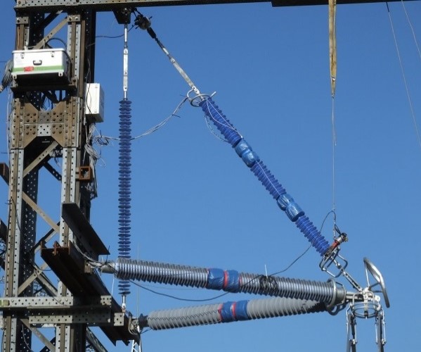
Figure 4 - Case study Germany 400kv compact line
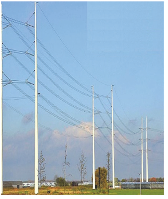
Figure 5 - Case study Germany compact line 400kv
Chapter 9 deals specifically with voltage uprating which requires the same analysis as line compaction. Line uprating examples from Manitoba Hydro and Norway are described (Figures 6 & 7).
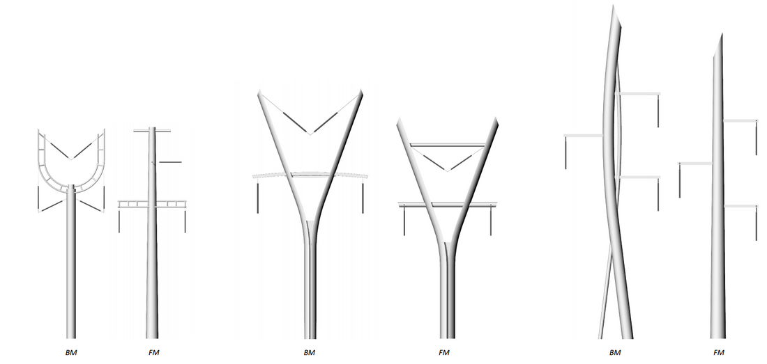
Figure 6 - Case study Norway tower considerations for line voltage uprating
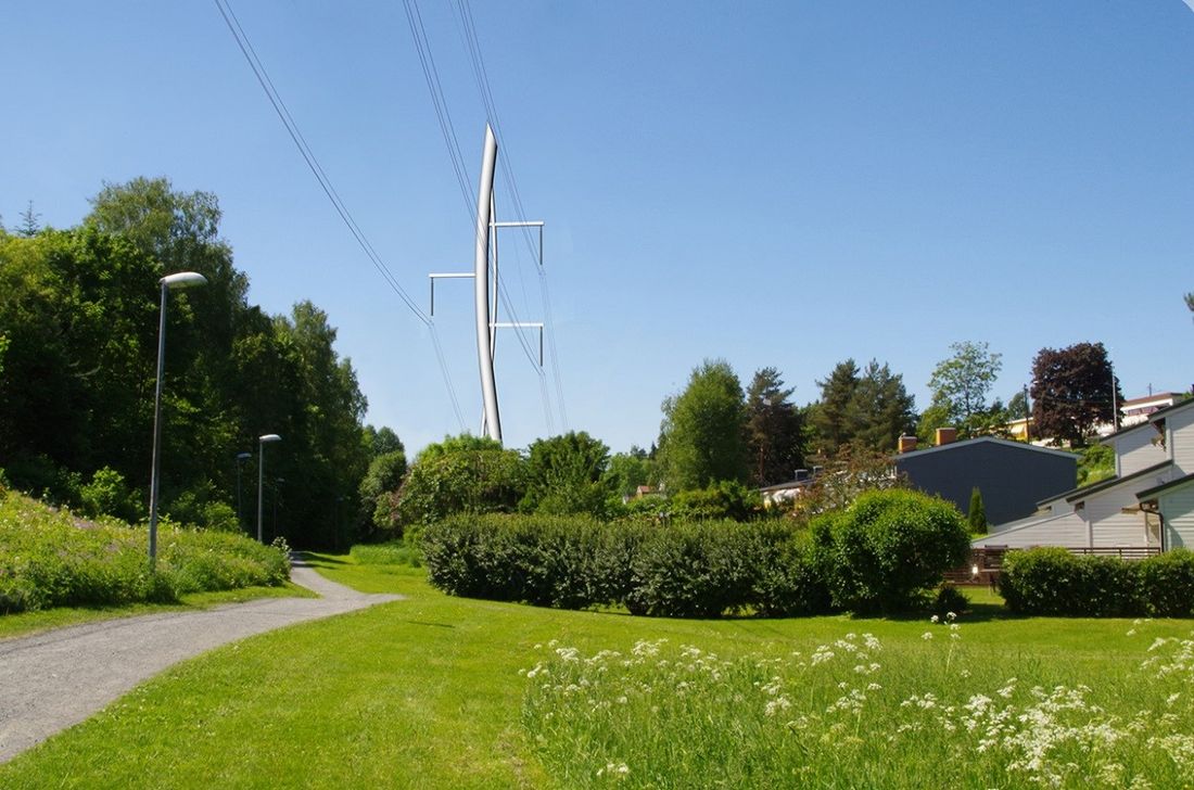
Figure 7 - straw tower configuration considered for Norway
The brochure does not cover the entire range of formulae and methods to design a compact line. It does provide the engineer with an overview of the parameters and the design options to apply. References are made to enable access for the engineer to understand and apply the detailed equations.
Conclusion
This brochure is a guideline that covers the main aspects relating to the design of compact lines. The main concept with regard to compact lines is that the electrical stresses are higher than with conventional lines. This higher stress manifests itself in the form of audible noise, compromised insulation co-ordination for switching and lightning impulses. This guide highlights these areas and allows the reader to understand the aspects that need to be taken into account when mitigating the effects of the higher electrical stress.
The calculation examples show the effect of different design solutions. The reader is able to optimise his solution initially from these examples prior to the detailed calculations that need to be performed on a specific design.
The case studies indicate different practical solutions that have been implemented. It includes a novel idea of supporting the conductor bundle with steel cables to reduce the sag. This allows for shorter spans hence narrower right of way. The voltage upgrade example indicates the same concept as a compact line with a different application for increased power flow. This example, although 40 years old, provides an example of the steps required for a reliable upgrade solution.
Note that the guide is not a design document but a document by which the reader can assess the aspects required for design of compact lines as well as determine the calculations that need to be undertaken in the completion of a detailed compact line design. It does, however, provide references that will enable the designer to fully design a compact line.
Other Technical Brochures