Field grading in electrical insulation systems
The purpose of the presented Technical Brochure is to introduce the theoretical concepts as well as the various practical implementations of electric field grading, which is a basic and essential measure of field control in many apparatuses of the electric power transmission and distribution system. Examples are cables and their accessories, plug‐in‐systems (connectors), bushings, rotating electrical machines, transformers or gas insulated systems. It further gives recommendations for modeling, characterization and standardization especially for nonlinear field grading materials and systems. It shall, thus, give designers as well as users of field grading applications technical guidance as long as international standards do not exist. It may also serve as an input to future standardization.
Members
Convenor
(DE)
V. HINRICHSEN
D. BACHELLERIE (FR), J. DAS (US), L. DONZEL (CH), M. HADDAD (UK),
M. HAGEMEISTER (CH), N. HAYAKAWA (JP), S. JOSEFSSON (NO), I.
JOVANOVIC (US), L. KEHL (DE), M. KOCH (DE), M. KOZAKO (JP), J. LAMBRECHT (DE), F. PERROT (UK), C. STAUBACH (DE), J. WEIDNER (DE), N. ZEBOUCHI (FR), M. H. ZINK (DE)
Young members : R. HUSSAIN (DE), M. SECKLEHNER (AT)
Corresponding Member : D. TABAKOVIC (US)
Introduction
Electric field grading – sometimes also denoted as stress grading – refers to the technique of effectively and reliably controlling the electric field distribution within or around a device.
Electric field grading in HV and EHV apparatus has evolved over the years from the application of simple geometries and homogeneous dielectrics with linear properties to complex systems that make use of designed composites. The composites are made of selected matrix materials and fillers with nonlinear permittivity (AC applications) or conductivity (DC applications) as well as functionally graded materials where the filler particles are deliberately spatially distributed to further optimize the utilization of the composites. The latter are currently in the introductory phase, and promising results have already been achieved.
The trend towards HVDC power transmission represents a challenge since DC stress requires in almost all cases to include the temperature effect in the technical evaluation of the field grading systems. The reason is that the electric conductivity is the dominant parameter for field grading in DC applications, and it is strongly affected by the temperature whereas the permittivity is not. Additionally, transient phenomena are much more difficult to handle in DC systems because the time constants of the transitions between resistive and capacitive electric field distributions may take extremely high values of up to several weeks or even months.
The purpose of the presented Technical Brochure is to introduce the theoretical concepts as well as the various practical implementations of electric field grading, which is a basic and essential measure of field control in many apparatuses of the electric power transmission and distribution system. Examples are cables and their accessories, plug-in-systems (connectors), bushings, rotating electrical machines, transformers or gas insulated systems. It shall, thus, give designers as well as users of field grading applications technical guidance as long as international standards do not exist. It may also serve as an input to future standardization.
The Technical Brochure summarizes the work carried out by Working Group D1.56 where the scope of the study is presented in Chapter 1 and the following main aspects are considered:
- Basics of electric field grading (Chapter 2)
- Material systems for field grading systems (Chapter 3)
- Simulation of field grading systems (Chapter 4)
- Applications (Chapter 5)
It ends with a conclusion and an outlook to future needs and developments (Chapter 6).
Structure of the Technical Brochure
Basics of electric field grading
Common uncertainties and misunderstandings of the terms geometric, capacitive, refractive, resistive, bulk, interface or surface, linear and nonlinear field grading are smoothed out in this chapter, in which a detailed theoretical overview of the different approaches is given (Figure 1).
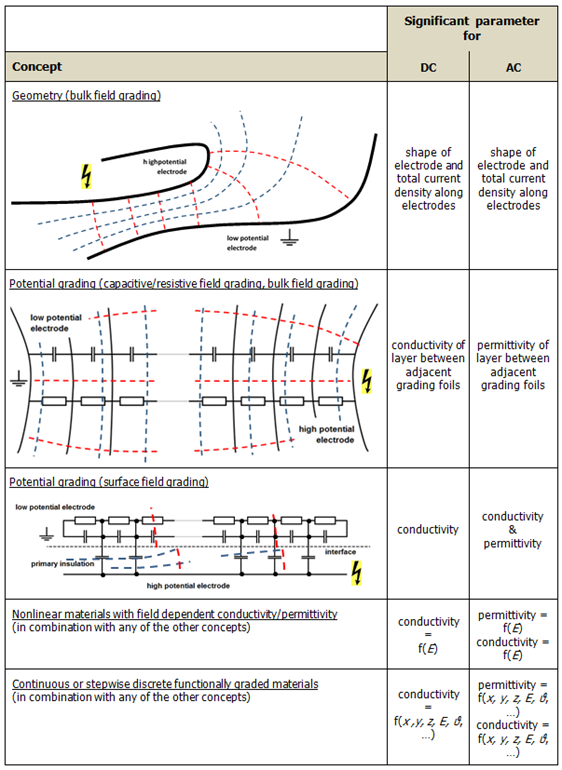
Figure 1 - Overview of electric field grading concepts
(red dashed lines = field lines, blue dashed lines = equipotential lines)
Complex field grading concepts based on nonlinear material properties as well as a quite novel field grading technology by functionally graded materials with non-homogeneous, spatially distributed electrical properties (permittivity, conductivity) are shown and analyzed in detail. Although apparatuses that would make use of it are not yet commercially available, practicable solutions have been published how to achieve functional grading by centrifugalizing filler powders of different mass densities and permittivities in the polymer matrix during the curing process (Figure 2).
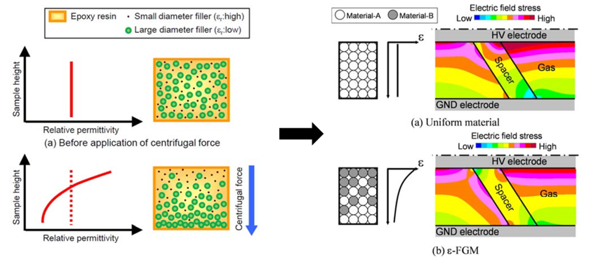
Figure 2 - Example of the field grading concept by functionally graded materials [1]
Finally, this chapter points out the potential and limitation of each individual field grading concept, which can be used to evaluate the advantages and disadvantages of these technologies.
Material systems for field grading systems
A comprehensive understanding of the various possible field grading systems (matrix materials and fillers) is an important basis for decisions on appropriate field grading systems in individual applications. By the knowledge of the specific properties and the different options, optimum approaches adapted to the intended functionality can be chosen. Pure materials with desired electrical properties, e.g. very high permittivity or well controlled conductivity, are directly applicable as field grading materials. However, these are typically ceramics, which have mostly unfavorable mechanical properties, and they cannot be directly used. Therefore, field grading materials are compounds in most cases, and detailed knowledge about the different electrical, mechanical and chemical properties of matrix materials and fillers is indispensable. Most of the matrix materials are polymers (thermoplastic polymers, thermoset polymers, elastomers), which are presented and discussed in detail in this chapter.
The fillers are used to tune either the permittivity or the conductivity of a material. The most widely used fillers are carbon blacks, mainly in the form of powders. Percolation theory must be well understood in order to achieve the desired electrical properties, which are very different for filler concentrations either below or above the percolation threshold.
It must also be considered that carbon particles tend to agglomerate in the manufacturing process causing inhomogeneities. A promising alternative for future developments with good electric conductivity are carbon nanotubes. These are microscopic tubular structures (molecular nanotubes) consisting of carbon atoms. They are commercially available but have not reached a broad range of application yet. Further development is still required to reliably control the manufacturing process to achieve a high degree of reproducibility as well as the intended results for the final product.
In many cases, especially in cable accessories or in rotating electrical machines, nonlinear field grading systems have turned out to be electrically very effective and quite compact. Field grading can be achieved by very thin layers of nonlinear electric properties. As fillers for nonlinear field grading materials either silicon carbide (SiC) particles or zinc oxide (ZnO) microvaristors are used in commercially available products. A new approach with antimony doped tin oxide (ATO) is still under investigation (Figure 3).
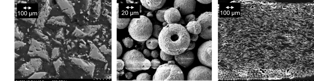
Figure 3 - Scanning electron microscopy pictures of SiC (left), ZnO (middle) and ATO particles [2]
SiC has been used for quite a long time but has some shortcomings such as only weak nonlinearity (which, however, is sometimes desirable), poor reproducibility of the electric properties and a mechanical hardness that causes strong mechanical wear of the manufacturing tools. These drawbacks are overcome by the use of ZnO microvaristors, which have been applied mainly to cable accessories since around the year 2000. The theory of both types of nonlinear fillers is discussed. Then, background information about some quite new approaches, like polyanilines (most often in the form of PANI-EB), graphene oxides and tin oxide (SnO2) as semiconductive coating of mica particles is provided.
A focus is also given to measurement metrics of field grading materials and systems. Matrix material, fillers and the resulting composites require different and independent approaches. For instance, the polymer matrix can be characterized by means of physical properties of the uncured polymer (rheology), as well as of the intrinsic physical properties of the cured polymer. This includes electrical properties (permittivity, tan d, bulk and surface resistivity with their E-field and temperature dependencies, breakdown strength, etc.), thermal properties (glass transition temperature, melting point, etc.) and mechanical properties (tensile, flexural and compressive strength, etc.). Detailed lists of all parameters of interest are presented, which give an idea about the manifold challenges in the design process of a new field grading system. A huge number of properties have to be regarded. The application of nonlinear field grading systems is comparatively new but has gained increasing importance with the currently emerging DC applications (DC cable accessories, DC gas insulated systems). The electrical characterization of nonlinear field grading materials gives rise to two major challenges: choosing appropriate models and termini to describe the electrical characteristics (e.g. as defined in Figure 4) and measuring these characteristics in a well-defined and reproducible way.
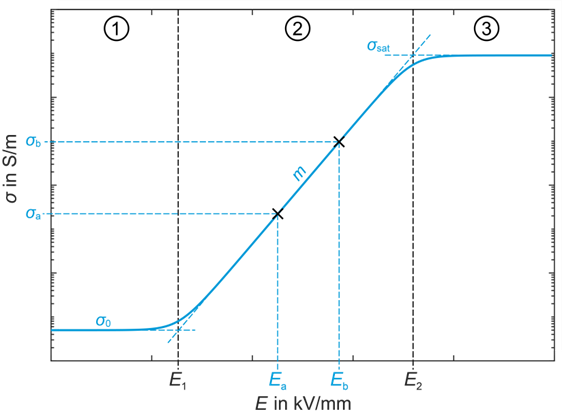
Figure 4 - Exemplary σ-E-characteristic of a nonlinear resistive field grading material. σ0 is the base conductivity, E1 is the switching field strength, m is the slope of nonlinearity, and σSat is the saturation conductivity [3].
A suitable terminology is proposed, and mathematical descriptions of the nonlinearity (conductivity as a function of the applied electric field) from the literature are presented. Not less important are clear rules for reproducibly characterizing the filler properties and those of the final composite. It has to be understood that it is still not possible to forecast the electrical properties of a compound just by electrically characterizing the filler. The resulting composite may have surprisingly different electrical properties. Systematically designing “tailored functionality” of nonlinear field grading systems thus remains a future goal and requires further research.
Simulations of field grading systems
Different methods can be used to design and optimize field grading systems. Historically, transient network analysis (TNA) has been used and is still helpful in special cases. However, nowadays numerical field simulations with the finite element method (FEM) or the finite difference method (FDM) are more widely used. The challenge for TNA is to build an equivalent circuit model representing the physical behavior of the system in a sufficiently accurate way (Figure 5). Limitation is given regarding the modelling of complex geometries.
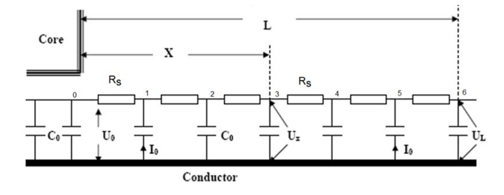
Figure 5 - TNA model of a typical end-turn configuration of the high-voltage coil of rotating electrical machine [4]
Though TNA simulations are possible and often applied even for thermo-electrically coupled physics, the rapid progress in electric field simulation software and consequently reduced need for expensive hardware enables not only highly-specialized users to perform nonlinear fully coupled 3D field simulations, which typically yield realistic and detailed results on electric field and temperature distributions (Figure 6).
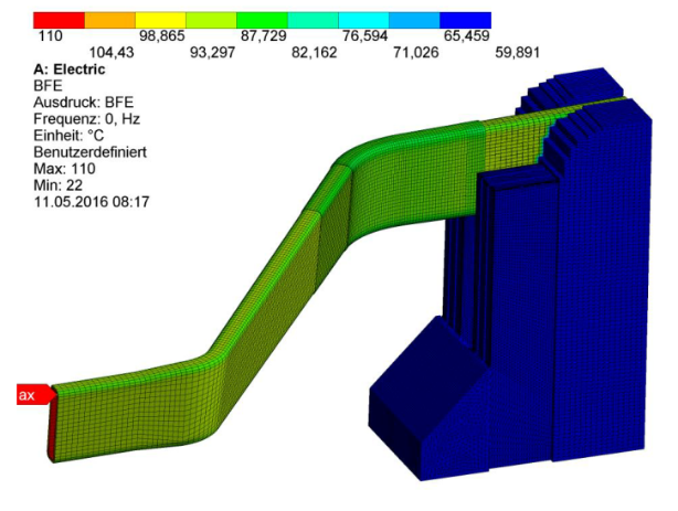
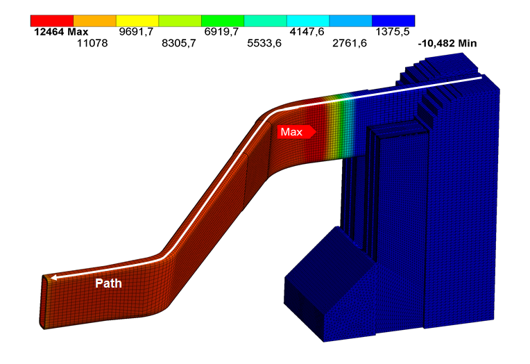
Figure 6 - Results for electric potential (left) and temperature (right) distributions of a generator stator bar with nonlinear field grading concept at the slot exit [5]
In general, experimental validation of the simulation approaches and results is mandatory. It is quite challenging to measure the electric field and potential distributions without influencing the potential and field situation significantly. The best way to do is to perform this capacitively, without direct contact to the surface. With this method the distortion is minimized but still present. A very effective approach is the use of Pockels sensors, which can give results of high accuracy in the time domain, and thus being applicable to DC, AC as well as transient field stressed systems (Figure 7). An example how this measurement technique is used in practice is given in this chapter for efficiency assessment of the end corona protection system used in rotating electrical machines.
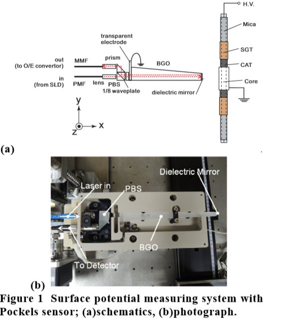
Figure 7 - Schematic view of a surface potential measuring system with Pockels sensor [6]
In special cases, such as for field grading concepts with resistive materials, an indirect assessment of the grading performance might be possible by thermal imaging as long as its surface is externally accessible. Another, indirect option to validate field simulation results is to measure partial discharge inception voltages, which are good indicators for excessively high electric field stress. On externally accessible systems this can be done either optically by UV sensitive “corona cameras”, but the more common and always applicable approach is to do it by “classical” measurements of apparent charges and evaluation of charge patterns.
Applications
Besides explaining the theoretical background and approaches of electrical field grading this Technical Brochure is intended to inform about the most important applications that make use of electrical field grading, and to address the related major challenges. The chosen examples of this chapter are cable accessories, plug-in systems and separable connectors, transformers, bushings, rotating electrical machines, and insulators.
MVAC and HVAC cable accessories are well established products where geometric and refractive field grading concepts are used. ZnO microvaristors based nonlinear resistive field grading material is employed for example in HVAC dry-type self-supporting cable terminations and in cold and heat shrink MVAC cable terminations as illustrated in Figure 8.
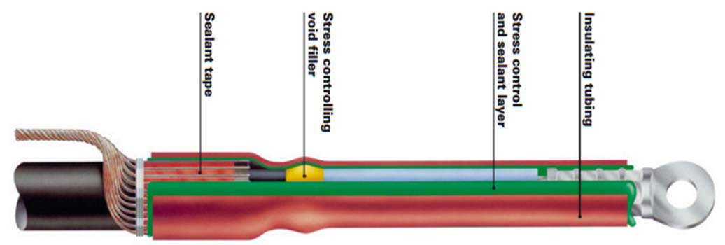
Figure 8 - Heat-shrink MV termination with integrated nonlinear refractive field grading layer
based on a hot-melt compound and embedded ZnO microvaristors [TE]
Most recent developments of cables and their accessories are for HVDC power transmission systems, where the ±320 kV level seems to be state of the art and ±550 kV and ±640 kV are under development. Main field grading principles for HVDC cables rely on nonlinear resistive grading, but also geometrical grading is applied to take care of transient voltages, using improved new rubber insulation materials with suitable DC conductivity and less formation of space charges. Figures 9 and 10 show a joint and a termination for a ±320 kV DC cable where a nonlinear resistive field grading layer is integrated. Though first type and prequalification tests on HVDC cables of 320 kV and above have been successfully passed, the technology is still not finally established and needs further development. An important driver for these activities are plans in Germany and other parts of Europe to implement DC underground transmission lines of several Gigawatts over several hundreds of kilometers.
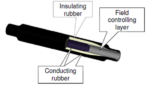
Figure 9: 320 kV DC cable joint with an integrated nonlinear resistive field grading layer [7]
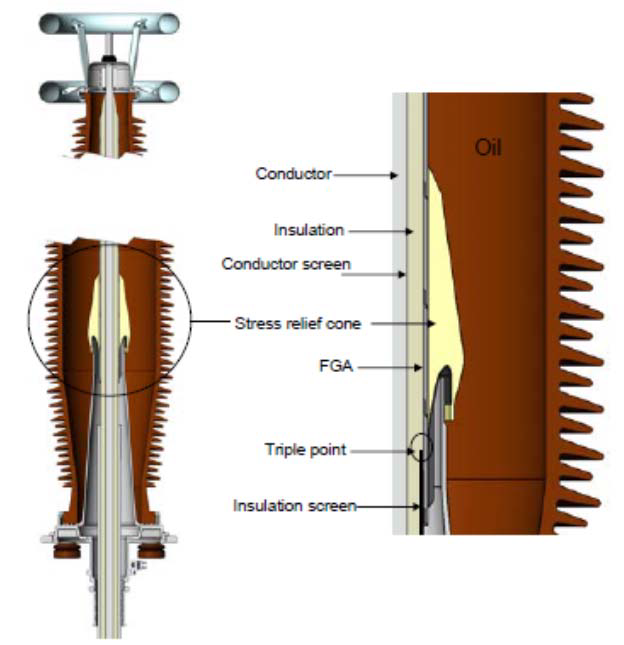
Figure 10: 320 kV DC cable termination [8]
Regarding plug-in systems and separable connectors, today outer and inner cone systems are available. The electric field inside a separable connector is typically graded geometrically with deflectors made from conductive materials such as carbon black filled elastomers. Alternatively, conductive varnish or coatings are used. In contrast to joints and terminations, where the electric strength of the interface between the cable insulation and the stress cone is decisive, separable connectors have an additional, very critical interface between the stress cone and the socket or bushing, respectively. Both interfaces have to withstand the applied voltage stress. For that purpose, a sufficiently high contact pressure between the layers must be ensured, which represents one of the main design challenges of these devices. While outer cone separable connectors are widely used for connections in the medium voltage range and lower transmission voltages (Us £ 72.5 kV), inner cone systems are available for system voltages up to 550 kV (AC). They require a metal encapsulation and are thus completely screened. Pluggable joints and terminations with nonlinear microvaristor filled field grading layers are also available to date.
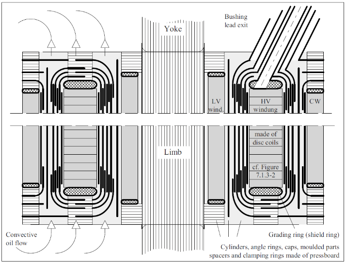
Figure 11: Insulation system of a classic high-voltage power transformer with core, low voltage winding LV, high-voltage winding HV and compensating winding CW (schematic representation from inside towards outside) [9]
Oil-barrier insulation systems were introduced into power transformers during the 1960s and are still state of the art (Figure 11). This pressboard barrier technology is based on liquid insulation, which has to ensure basic electric strength by filling and impregnating the whole transformer’s insulation structure, while the solid insulation is used to form barrier systems dividing highly stressed oil channels into smaller sections. The subdivision of long oil gaps effectively reduces the hazard of formation of long particles and fibre bridges in the highly stressed E-field zones. Additionally, it permits higher field stress and requires less space, hence leading to lower costs compared to full oil insulation.
Today, new natural ester-based fluids become increasingly attractive, and occasionally the end user wishes to retrofit existing transformers with a new insulation fluid. However, ester fluids have higher permittivities than mineral oils, and sometimes unexpected effects on the internal field grading have to be regarded when changing the overall insulation system of a transformer.
Special attention is required for converter transformers, as the oil-pressboard combined insulation near the valve side is exposed to a composite AC-DC voltage. The design of the insulation system of transformers used for HVDC applications is quite different to that of transformers for AC applications. The basic research on the dielectric behavior under DC stress especially of liquid insulating materials and the interfaces to solid insulation is still ongoing. The focus of the research activities is on the physical mechanisms contributing to oil conductivity, i.e. charge carrier generation, transport and recombination as well as the formation of space charges and the interaction of liquid and solid barrier interfaces (surface charges). For analyzing the DC behavior of the materials, methods like the pulsed electro-acoustic (PEA) method or measurements using the Kerr-effect of dielectric liquids allow the direct investigation of materials under DC. The research leads to a significantly new understanding of the insulation systems, and hence it may be that in future new design rules and methods for modelling the behavior of transformer insulation systems under DC stress will be introduced.
High-voltage bushings are used to guide a conductor that is on HV potential through a grounded wall, e.g. the tank of a transformer. Ungraded bushings can only be used for rather low voltages because of the low inception voltage of surface discharges upon the insulation. For medium voltages geometrically graded bushings are typically used, whereas for voltages above approx. 70 kV geometrically and capacitively graded bushings are required. Recent developments of compact high-voltage bushings make use of layers of nonlinear field grading material, for instance a microvaristor filled epoxy resin layer, which is directly applied to the outer surface of a hollow core insulator as an interface between the glass-fibre reinforced plastic tube and the weather sheds (Figure 12). This allows for very compact designs with simplified internal geometric grading measures, referred to as “slim bushings” in the literature.
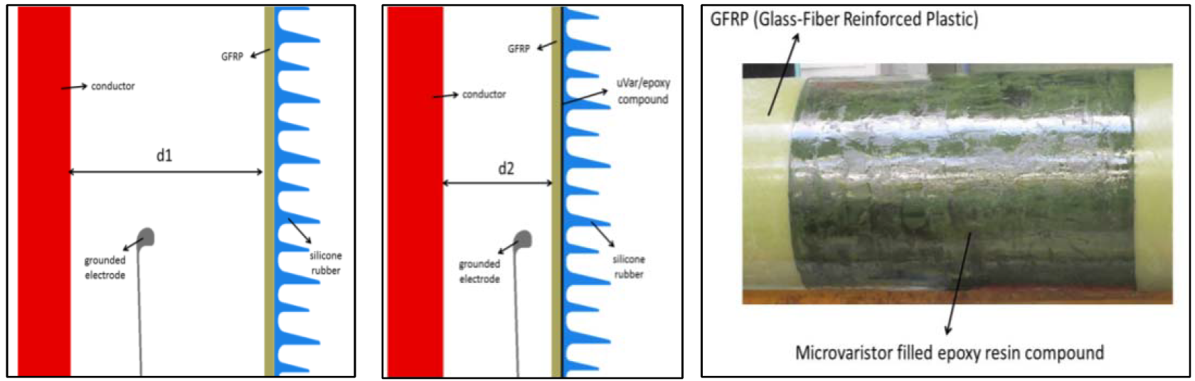
Figure 12 - Conventional geometrically graded bushing (left) and a microvaristor controlled “slim” bushing (middle); details of microvaristor application (right) [10]
In rotating electrical machines, field grading is applied to suppress local field enhancement at the stator slot end. This field grading system, often called “end corona protection,” is mandatory for machines with rated voltages of approximately 6 kV and higher. The mechanical, thermal and electrical operating conditions of these insulation systems are extremely demanding (Figure 13).
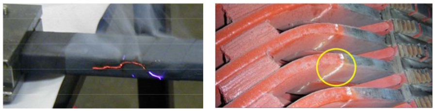
Figure 13 - Tracking failure caused by thermal overstressing (left) [11] and indication of PD deterioration [12] in the field grading system
Depending on the manufacturing process or the stator bar design, tapes or varnishes are nowadays used for field grading. Typically, moderately nonlinear SiC fillers are applied. Alternatives have been investigated, e.g. based on ZnO microvaristors or tin oxide, but they could not replace classical concepts so far. While each layer of a varnish can be electrically adjusted by using different types or amounts of filler particles, tapes have a defined electrical resistance characteristic, pre-defined by the tape manufacturer. This disadvantage has to be compensated by painting different lengths of layers or by wrapping different types of tapes stepwise. The resulting innumerable degrees of freedom need a comprehensive understanding of the system behavior and many years of design and operating experience.
Converter fed drives require special approaches. Electric field grading materials that perform satisfyingly under power-frequency (50/60 Hz) may experience a premature failure when exposed to pulse width modulated (PWM) voltage source converters (VSC). Grading materials designed for power-frequency applications may not be capable of controlling the stress caused by high dU/dt on the surface of the winding ends (Figure 14).
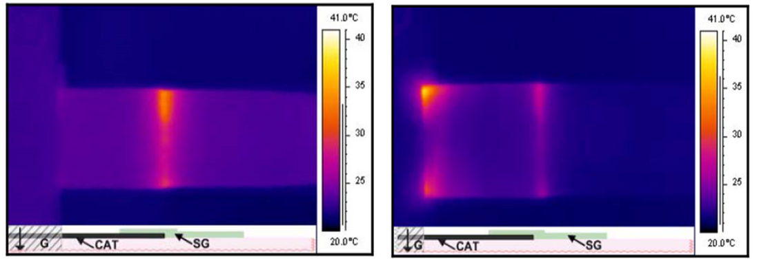
Figure 14 - Hot-spot development in the field grading region outside of the simulated slot for switching frequencies of 5 kHz (left) and 50 kHz (right) [13]
Also, the performance of “simple” insulators can principally be improved by electric field grading measures. For ceramic line insulators resistive glazing has been applied in order to improve the performance under pollution, but without greater success. A similar approach was investigated for composite line insulators by applying a nonlinear, microvaristor based layer, but has not gained major importance as well (Figure 15).
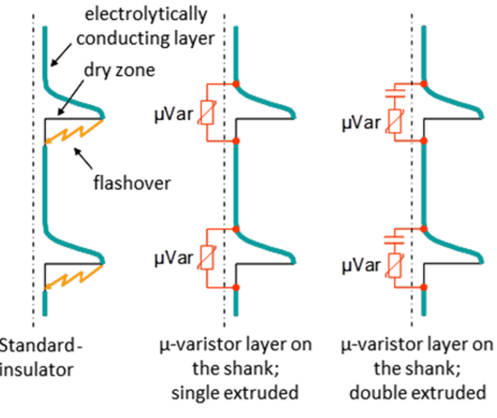
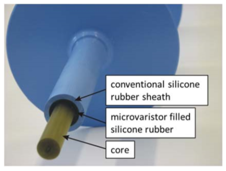
Figure 15 - Model of dry zone arcing suppression by a capacitively coupled microvaristor layer (left) [14] and non-ceramic line insulator with microvaristor filled silicone rubber layer [15]
Conclusion and outlook to future needs and developments
This Technical Brochure provides a broad overview about electric field grading concepts, as well as explaining special aspects in detail. It further gives recommendations for modeling, characterization and standardization especially for nonlinear field grading materials and systems, which may be used as input for future standardization of requirements and adequate test procedures. So far there are no standardized approaches for neither of these aspects. But without such standards nonlinear grading systems are extremely difficult to develop, as typically all manufacturers of fillers or of final composites may choose different approaches of characterizing their products. Today it is hardly possible to communicate the requirements on a filler in order to develop a tailored grading system. Too many parameters are defined and determined in different ways by different manufacturers. Especially, the application of highly nonlinear resistive field grading systems in MVAC and HVAC apparatus is limited to some extent by the fact that relevant standards usually require to perform AC withstand tests at comparatively high levels in order to ensure safety margins based on historic data. With the integration of nonlinear field grading systems into modern designs this may cause overloading and overheating or even local destruction of the field grading during testing. Future new standards or new editions of existing standards may have to take this into account.
Future developments might be the application of 3D printing, which seems to be a very promising means of easily creating spatially and functionally graded insulators and HV equipment, and which is currently under investigation. HVDC insulation and corresponding field grading systems will gain in importance, as well as “smarter” insulation systems that self-adapt their electrical and mechanical properties to the actual environmental and operational service conditions. One basic challenge especially with novel, nonlinear field grading approaches is the lack of nonlinear fillers available on the market. Applications like cable accessories, insulation of rotating electrical machines, line and hollow core insulators or high-field GIS insulators require very different degrees and a wide range of nonlinearity and “switching” field strengths, i.e. the field strength necessary to make the material become more conductive. The market for such applications is possibly too small or the need for performance improvement too low to drive the development of such materials for novel applications. A systematic and predictive tailoring of nonlinear field grading systems is, therefore, not yet possible, and current approaches are often “trial and error” based with unexpected and surprising, sometimes wanted, sometimes unwanted results. Besides the lack of suitable filler materials, also the lack of standardization is still impeding a development into this direction.
References
- Hayakawa, N.; Kato, K.; Okubo, H.; Hama, H.; Hoshina, Y.; Rokunohe, T.: Electric Field Grading Techniques in Power Apparatus Using Functional Materials. CIGRE Paris Session, D1-309, Paris, 2014
- Staubach, C.: Herausforderungen bei Auslegung und Betrieb von nichtlinear resistiven Feldsteuerungssystemen in Kabelanlagen, 94. Kabelseminar, Hannover, 2019
- Secklehner, M.; Hussain, R.; Hinrichsen, V.: Tailoring of new Field Grading Materials for HVDC Systems. INSUCON 2017, Birmingham, 2017
- Kogan, V.; Dawson, F.; Gao, G.; Nindra, B.: Surface corona suppression in high-voltage stator winding end turns. Proceedings: Electrical Electronics Insulation Conference and Electrical Manufacturing & Coil Winding Conference, 1995
- Staubach, C.; Hildinger, T.; Staubach, A.: Comprehensive electrical and thermal analysis of the stress grading system of a large hydro generator. IEEE Electrical Insulation Magazine Volume: 34, Issue: 1, January-February 2018
- Kumuda, A.; Kiuchi, K.; Ikeda, H.; Hidaka K.; Boggs, S. A.; Tsuboi, Y.; Kisakibaru, T. Yoshimitsu, T.: Potential Distribution Measurement on Stress Grading System of High-Voltage Rotating Machines with High Temporal Resolution by Pockels Sensor. INSUCON 2013, Birmingham, 2013
- A. Ericsson, M. Jeroense, J. Miller, L. Palmkvist, B. Railing, P. Riffon: HVDC Light Cable Systems - The latest Projects. Nordic Insulation Symposium (Nordis), Tampere, June 11-13, 2003
- Sorqvist, T.; Christen, T.; Jeroense, M.; Mondiet, V.; Papazyan, R.: HVDC Light Cable Systems-Highlighting the accessories. 21st Nordic Insulation Symposium (Nordis 2009), Gothenburg (Sweden), June 15-17, 2009.
- Küchler, A.: High-voltage Engineering - Fundamentals - Technology - Applications. Springer Vieweg 2017, ISBN 978-3-642-11992-7
- Ye, H.; Clemens, M; Schulte-Fischedick, J.; Seifert, J.: Investigation of Electrical Field Grading of Bushings with Microvaristor Filled Epoxy Resin. 2014 IEEE International Power Modulator and High-voltage Conference (2014 IPMHVC), Santa Fe, USA. 2014.
- Baumann, T.: Electrical Stress Grading Systems for Generators with Rated Voltages above 20 kV. ETG-Workshop „Feldsteuernde Isoliersysteme“, Darmstadt, 2011
- Stone, G.C.; Sascic, M.; Dunn, D.; Culbert, I.: Recent problems experienced with motor and generator windings. IEEE PCIC, 2009
- Sharifi-Ghazvini, E.: Analysis of Electrical and Thermal Stresses in the Stress Relief System of Inverter Fed Medium Voltage Induction Motors. PhD thesis University of Waterloo, ON, Canada, 2010
- Hinrichsen, V.; Küchler, A.: Grundlagen der Feldsteuerung. ETG Workshop "Feldsteuernde Isoliersysteme", 22. & 23. November 2011, Darmstadt, 2011
- Debus, J.; Hinrichsen, V.; Seifert, J.: Improved Performance of Silicone Rubber Composite Insulators by Micro-Varistor filled Components. XVII International Symposium on High-voltage Engineering, Hannover, Germany, 2011
Other Technical Brochures