Sheath bonding systems of AC transmission cables - Design, testing, and maintenance
This Technical Brochure considers lifecycle aspects related to sheath bonding systems of AC transmission cables, from design and installation to operation and maintenance. This brochure reviews relevant industry standards and specifications, reviews information and requirements needed to design such sheath bonding systems, reports industry best practices, and provides recommendations, to ensure effective connection and insulation of such systems.
Members
Convenor
(US)
T. ZHAO
Secretary
(US)
R. BASCOM
C. GRODZINSKI (CA), H. NYFFENEGGER (CH), W. WANG (CN), R. OLSEN (DK), G. DENCHE (ES), M. NGUYEN-TUAN (FR), N. COUTURIER (FR), J. PILGRIM (GB), L. COLLA (IT), S. MASHIO (JP), P. VAN VELZEN (NL), O. CAKMAK (TR), T. DU PLESSIS (ZA), G. BUCEA (AU), N. RIBEIRO DE LOUREDO (BR), TONI WUNDERLIN (CH)
Introduction
This Electra article provides a high-level summary outcome for the Technical Brochure developed by CIGRE Work Group B1.50 on sheath bonding systems of AC transmission cables. This Technical Brochure (TB) considers lifecycle aspects related to such systems, such as, design, installation (including after installation testing), and maintenance thereof.
Sheath bonding is required for cable systems to ensure effective connection and insulation coordination of the cable, metal sheath, armouring, insulating jacket, and semi-conductive outer sheath covering to earth. Incorrectly configured sheath bonding systems may lead to cable system failures, including unintended cable rating reductions, additional system losses, and possibly pose safety risks.
The Working Group reviewed relevant industry standards and specifications, reviewed information and requirements needed to design such sheath bonding systems, reported industry best practices, and provided recommendations for sheath bonding used on AC transmission cable systems. The reviewed example documents included Electra 128-1990, TB 189-2001, TB 268-2005, TB 283-2005, TB 347-2008, TB 403-2010, TB 556-2013, and TB 680-2017.
The Technical Brochure focused on AC transmission cable systems rated at operating voltages at and above 66 kV. Such systems always require a uniquely designed sheath bonding system. The sheath bonding system design performed for each individual cable system allows for the selected type of cable and accessories used, specific site installation conditions, and electrical system parameters to which the cable system is connected.
These sheath bonding system designs are also required for cable systems of lower operating voltages (<66 kV), where the same principles as described in this Technical Brochure for AC transmission cable systems are applied in a more standardised approach. Although this standardised approach requires thorough studies and critical engineering considerations, the scope of Working Group B1.50 did not formally include investigations and descriptions of such standardised approaches.
The Technical Brochure is effective to provide definitions, descriptions and requirements for system components and parts that form part of the sheath bonding systems and that should be considered as part of the sheath bonding system design, testing, installation, operation, and maintenance.
The Technical Brochure further addresses maintenance of these sheath bonding systems by providing recommendations on correct maintenance and applicable testing criteria of the sheath bonding system components such as sheath voltage limiters. The Technical Brochure also considers the impact of the bonding configuration on monitoring systems
Scope/Methodology
The scope of the brochure applies to sheath bonding systems on AC transmission cables. The scope of the work is to recommend best practices on sheath bonding systems in lifecycle phases from designs to operation and maintenance. The brochure includes the following main topics:
1. Basic information about sheath bonding systems
-
Provide an overview of bonding system functions.
-
Review existing documents and other related engineering information.
-
Review service experience depending on bonding schematics, standing voltage and withstand levels.
2. Design of sheath bonding systems
-
Consider different bonding designs: single point, multiple point (solid), cross-bonding, and discuss different challenges regarding screen protection of cable systems, including joints, terminations and link boxes.
-
Provide basic knowledge (voltages, current rating, and energy absorption) for selection and implementation of bonding leads, link boxes, and sheath voltage limiters, depending on cable system parameters and bonding system designs.
-
Provide recommendations for bonding system insulation coordination.
-
Provide guidance on cable system models for overvoltage calculations.
3. Testing of sheath bonding systems
-
Provide guidance on testing of sheath bonding system components.
-
Provide guidance on testing of sheath bonding systems after installation.
4. Maintenance of sheath bonding systems
-
Provide recommendations on maintenance of bonding systems including sheath voltage limiters.
-
Provide testing criteria while considering interference with implemented monitoring systems.
-
Discuss monitoring of bonding systems.
The methodology applied by the working group to address this scope of work was to perform a review of existing publications on the topic as summarised in Chapter 1 of the technical brochure and to obtain, via working group members, surveys of respective national knowledge and in-service experience on the latest trends and developments on sheath bonding systems designs, testing, installation and maintenance. The surveys contained specific questions related to the design, operation and maintenance practices applied within utilities, resulting responses that are less often found in formal publications.
Description of the Technical Brochure
The Technical Brochure consists of five chapters and four annexes. The main outcome for the brochure chapters is summarised as follows:
Chapter 1 – Basic information of sheath bonding systems
This chapter of the document provides an overview of sheath bonding system functions and requirements through the review of existing documents and other engineering information related to sheath bonding systems. It furthermore includes the service experience and feedback received in terms of sheath bonding system configurations, schematics, standing voltages, and voltage withstand requirements.
Chapter 2 – Sheath Bonding system design and protection
This chapter lists and discusses the most commonly used sheath bonding system methods for the design of AC cable systems (i.e., single point, multiple point (solid), and cross-bonding) and the challenges regarding the insulation protection of cable system sheaths and insulating jacket. The TB provides basic knowledge on voltage withstand requirements, current ratings, and energy handling capability for the selection and implementation of bonding leads, link boxes and sheath voltage limiters, depending on the cable system parameters, sheath bonding methods, earthing connection and insulation co-ordination study results. The TB also provides guidelines for performing insulation co-ordination studies related to the design and voltage withstand requirements of sheath bonding systems, and the cable system models that can be used for computer software overvoltage calculations and simulations.
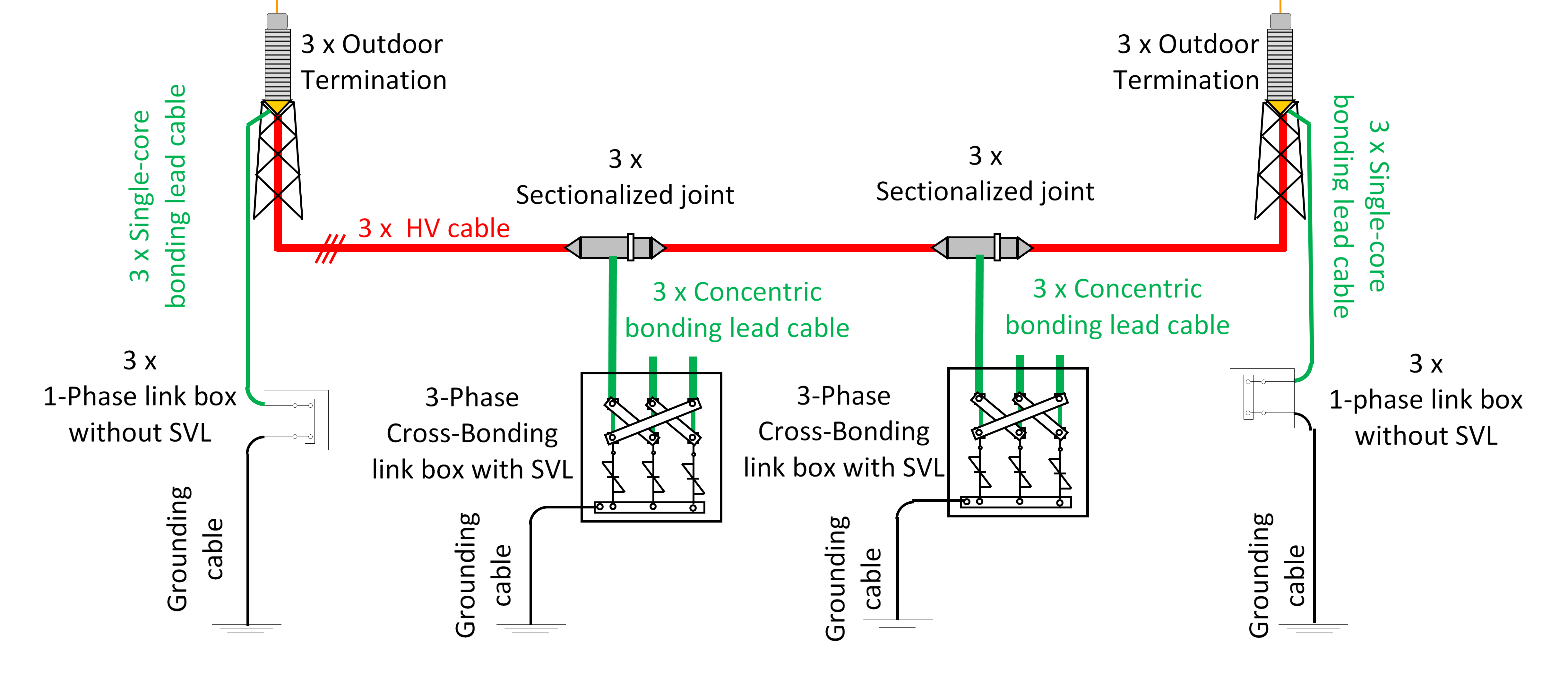
Example of a cross-bonding system
Chapter 3 – Testing of sheath bonding systems
Testing of sheath bonding systems is discussed in detail to provide guidance on type testing of bonding system components and equipment, and on performing after installation tests.
Chapter 4 – Maintenance of sheath bonding systems
Maintenance is addressed in this chapter by providing recommendations on industry best practices for maintenance of sheath bonding systems (including sheath voltage limiters and testing criteria). Condition monitoring options for the sheath bonding systems are also discussed as part of this chapter.
Chapter 5 - Conclusions
In the conclusion section of the technical brochure, a summary of the achieved deliverables is reported as follows:
-
A general overview and detailed definition for insulated cable system sheath bonding systems.
-
Functionality, detailed description, and listing of available standards for insulated cable system sheath bonding systems and for other cable system components that form part of the sheath bonding systems.
-
A literature review of available published international standards, guidelines, CIGRE Technical Brochures, and papers to summarise available information on sheath bonding systems. This includes a quick reference table for key design, testing and maintenance aspects required for sheath bonding systems.
-
A survey review to obtain service experience on sheath bonding system design, testing and maintenance. That includes a summary of responses from member countries for all key design, testing and maintenance aspects required for sheath bonding systems.
-
A detailed chapter on the design and insulation protection of sheath bonding systems, that describes: the standard type of known sheath bonding system designs; calculation formulas, calculation formula references and examples for sheath induced voltages and circulating currents on sheath bonding systems; sheath voltage limiter selection and application guidelines; sheath bonding system overvoltage calculation models and software references for power frequency and transient network conditions; and insulation co-ordination study requirements for sheath bonding systems.
-
A detailed chapter on testing requirements of sheath bonding systems, that includes both type testing and commissioning testing tables and references for known testing standards or CIGRE Technical Brochures. A critical finding by the WG B1.50 is that an insulation co-ordination study shall be performed for each specific project performed to establish the sheath bonding system voltage withstand ratings required for both overvoltage and transient conditions.
-
A detailed chapter on sheath bonding system maintenance requirements, with a further consideration for online and offline maintenance activities and scheduling thereof.
Annexes
The Technical Brochure includes annexes for the lists of abbreviations, term definitions, symbols, references, review of service experiences, and review of maintenance practice.
Conclusions
The brochure was effective in reviewing and providing the users with guidance on the best practice for sheath bonding systems that form a critical part of the AC transmission cable systems owned and operated in large quantities throughout the continents and countries in the world. The number one priority of these systems is to ensure safe and reliable performance of cable systems and to ensure the safety of personnel and equipment in proximity or contact with these cable systems. The working group participated in various meetings and engagements to combine all knowledge and best practice for these sheath bonding systems used on AC transmission cables, with the goal of ensuring that the technical brochure is effective in its content and purpose to recommend and define best practice for the cable system industry to design, install, test and maintain these sheath bonding systems.
A further expansion on some of the aspects covered in this Technical Brochure can be the work currently in progress by other CIGRE Working Groups such as JWG B1/C4.69 on the insulation co-ordination of AC cable systems and WG B1.60 on maintenance on HV cable systems, both of which may include an expansion of some of the critical engineering considerations for sheath bonding on AC transmission cable systems.
Other Technical Brochures