Guide for electromagnetic transient studies involving VSC converters
The Technical Brochure aims to provide comprehensive, documented, and validated descriptions of transients and associated ElectroMagnetic Transient (EMT) models and studies for VSC-HVDC converters. The objective is also to educate parties involved in VSC-HVDC projects (but not in charge of the converter station design), to explain what type of EMT studies shall be performed in the life cycle of VSC converters.
Convenor
(FR)
S. DENNETIERE
Secretary
(FR)
P. RAULT
T. PRIEBE (GE), S. BECKLER (GE), H. SAAD (FR), S. ELIMBAN (CA), E. PRIETO ARAUJO (SP), J. BEERTEN (BE), R. TENÓRIO (BR), A. ROGERIO (BR), J.C. GARCIA ALONSO (CA), J. VELÁSQUEZ (DE), Z. YUEBIN (CN), H. SURIYAARACHCHI (CA)
Introduction
The scope of the Technical Brochure has been restricted to point-to-point VSC-HVDC systems with MMC topology in the symmetrical monopolar configuration as they are currently the most frequent application of VSC-HVDC. Even though DC overhead lines, HVDC connection of wind farms, and multi-terminal/DC grids are outside the scope of this Technical Brochure, recommendations of the Technical Brochure can be slightly adjusted to be applied to these topologies. All simulations and analyses shown in the Technical Brochure are done with EMT simulation tools.
Before starting with the analysis of transients, the Technical Brochure describes the main converter station configurations. Converter topologies and main equipment are listed and their functions are explained. As C&P systems play a major role in the dynamic performance of the VSC, a general description of the main functions is provided.
EMT studies over the life cycle of VSC-HVDC systems
During the life cycle of a VSC-HVDC project, many parties are involved from the planning stage to maintenance and operation. EMT simulations are used intensively by HVDC manufacturers and utilities to design and test performance of the scheme used for the project. Manufacturers and utilities have considerable experience in modelling and studying the VSC-HVDC schemes. However, the correct modelling of the system into which the HVDC system shall be incorporated is of high importance as well. The input for the EMT models is a combination of customer information and supplier models. This is why the parties, that provide this data, need to understand the goals of all studies at each stage of the project and the required level of detail. Figure 1 provides an example of input/output data for transient stresses/insulation coordination study.
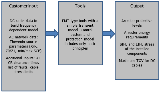
Figure 1 – Example of input/output for transient stresses/insulation coordination study
Transients during normal operation
Description and analysis of transients start with normal operation. This includes setpoint changes, connection/disconnection of loads, and the impact of different control strategies. As shown in Figure 2, start-up solutions are also evaluated to show their impact on transients. Some typical switching events on the AC grid are analysed with a VSC-HVDC link in close vicinity. Typical transients in black start conditions are also presented in the TB.
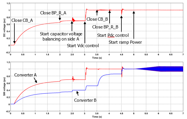
Figure 2 – Example of normal operation - Pole-to-voltage and submodule voltage during start-up
Grid side transients analysis
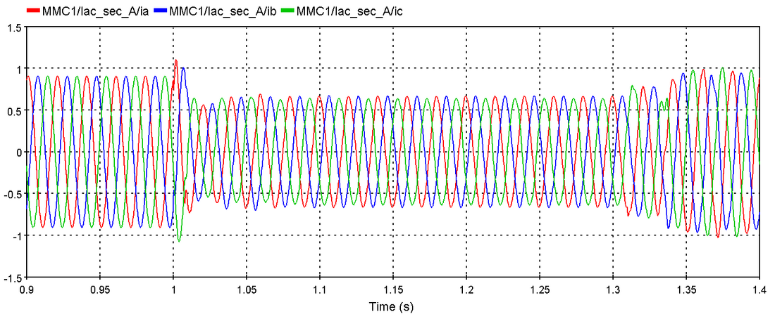
EMT studies of grid side events (mainly AC faults) are performed to determine stresses on equipment of the VSC-HVDC system. Additionally, these studies are necessary to analyse the dynamic behaviour of VSC-HVDC controls during transient events including their contribution to the AC network. Figure 3 presents results of 1-phase-to-ground AC fault with different negative sequence controller.
In real projects, these studies are used to identify the worst-case scenarios that can occur, as well as to demonstrate compliance with grid code requirements and analyse the impact of the HVDC system performance on the AC system.
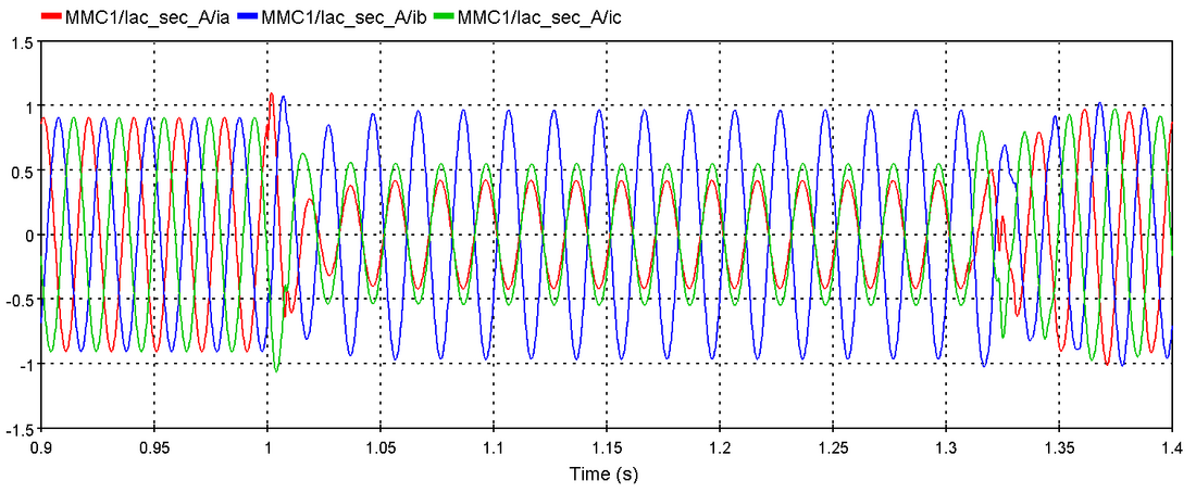
(a) converter-side currents without negative sequence controller
Figure 3 – Example of onshore grid transients - 1ph-ground fault typical waveforms
(b) converter-side currents with negative sequence controller
Figure 3 – Example of onshore grid transients - 1ph-ground fault typical waveforms
DC side transients analysis
DC side transients following faults or switching actions on the DC side or within the converter itself cause significant voltage and current stresses for all the equipment inside the converter station as well as on the DC transmission link such as DC cables, DC overhead lines, and cable junctions. During DC side transients, the system should be protected quickly to avoid any damage to the equipment. DC side transient simulations are conducted to determine thermal stresses, structural forces, and/or dielectric stresses which the different equipment must withstand as well as the air clearance required for safe operation. Figure 4 shows an example of DC grid transients. These are internal bus voltages for a pole to ground DC fault.
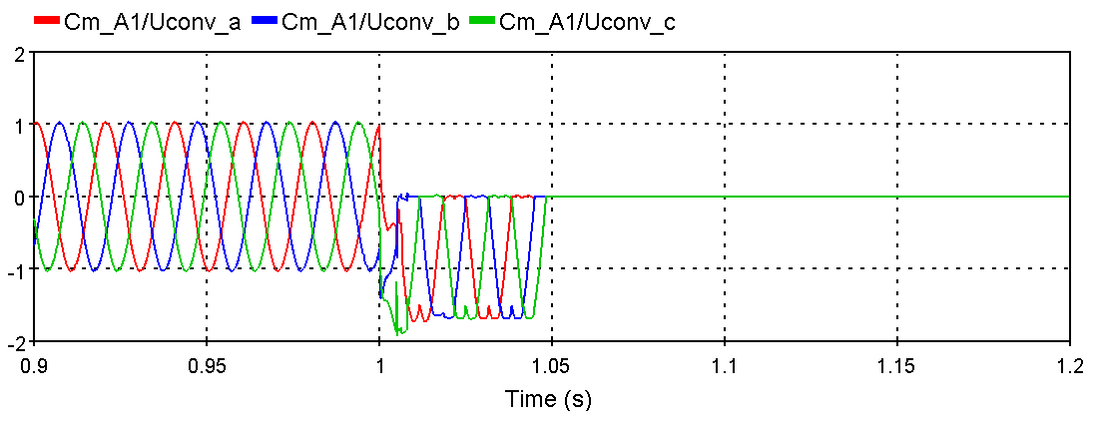
Figure 4 – Example of DC grid transients - Internal bus voltages for a pole to ground DC fault
Interaction Studies
The increasing integration of PED (Power Electronic Devices) within the AC network leads to a higher risk of interaction within such systems between PED, (passive) network elements, and/or conventional power plants. In addition to that, studying interaction issues influenced by PED is challenging due to:
- Complexity of PED C&P systems
- High PED influence on the power system
- C&P algorithm confidentiality
- Different software tools, versions, and simulation parameters for the provided models for each PED
- Model maintenance throughout the VSC-HVDC system life cycle
The TB provides guidelines for analysing interactions with EMT tools depending on the type of interactions. This chapter reflects the state-of-the-art phenomenon understanding and the methodologies described which are expected to evolve in the future with increased integration of PED.
Figure 5 provides an example of high frequency interaction.
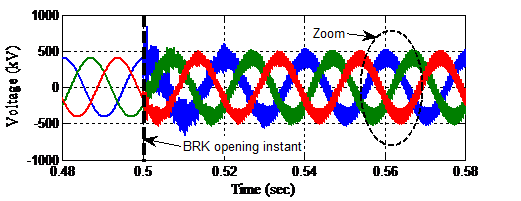
Figure 5 - Example of interation with power electronics - High Frequency Interaction Between Converter and Grid
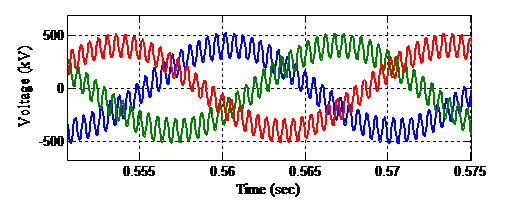
Figure 5 - Example of interation with power electronics - High Frequency Interaction Between Converter and Grid
Conclusion
The Brochure provides guidance to parties involved in VSC-HVDC EMT studies. First by describing the differents EMT studies at different stage of a project. It should help customers to anticipate the need for ressources and data during a project. Then, thanks to a large collection of typical waveforms, well documented, it provides reading keys to engineers who would like to analyse transients in VSC-HVDC converter stations obtained from EMT simulations or events recorded in the field.

Other Technical Brochures