Reliability Analysis and Design Guidelines for LV AC Auxiliary Systems
This article is a summary of the activates of CIGRE WG B3.42 (Reliability analysis and design guidelines for LV AC/DC Auxiliary Systems). The group produces two technical brochures on the LV AC auxiliary system and LV DC auxiliary system respectively. In this technical brochure (TB) on the LV AC auxiliary system, we primarily focus on the AC auxiliary system in substations, converter stations, thermal power plants and hydropower plants.
Convenor
(CN)
J. FAN
Secretary
(IE)
C.J. ROY
M. RIDGLEY (AU), Y. CHEN (CN), A. RIDLEY (UK), A. BURGOS MELGUIZO (ES), K. CHEN (CN), C. OBERTHUER (DE), M. ZIELIŃSKI (PL), H. ABDULLA (SA), J. LI (CN), H.R. SHARIFNIA (US), Y. LUO (CN), J. PIŁAT (PL), J.J. PLACID (CA), M. ARRAMBIDE (BE)
Introduction
LV AC auxiliary system provides essential power supplies for the auxiliary equipment such as pulverised coal feeders, forced draft fans, lubricating oil pumps, seal oil pumps for hydrogen cooled generators, protective devices, etc. The auxiliary equipment provides significant support to key primary equipment such as boilers, generators, converter valves and power transformers. Its safe and reliable operation is critical to power generation, transmission and distribution.
In order to achieve a reliable system, overall considerations need to be made. System structure, equipment selection, power supply of load, system operation and maintenance are all critical elements to be considered for the safe and reliable operation of the auxiliary power system. These elements are also the main concerns of this Technical Brochure.
Scope
The main scope of this WG was to investigate and produce design guidelines on the configuration, operation and maintenance of auxiliary systems for substations, converter stations, cable tunnels and power plant. This technical brochure provides the basic requirements for system design, equipment selection as well as operation and maintenance.
Description of the TB
The expansion of power systems around the world, coupled with the increasing application of network automation, power electronics and smart grids, is resulting in a greater need than ever for reliable and secure auxiliary power systems. However, the details of the design for auxiliary power systems has received little attention, and there is a lack of systematic research. Characterised by complicated networks, various types of loads and widely distributed circuits, auxiliary power systems around the world frequently experience issues such as inappropriate capacity, poor architecture, unsuitable coordination of protective equipment and insufficient supervision.
This Technical Brochure outlines the requirements for a safe and reliable auxiliary power system of power plants, substations and converter stations in separate chapters. The most complicated design is thermal power plants due to their complex system structures and large amounts of auxiliary equipment scattered over a vast area. The author spent a lot of effort in illustrating loads classification methods and their unique requirements of power supply strategy, the merits of different auxiliary power sources and their combined applications, and power distribution network to loads. It enables the reader to get a whole view of LV APS installed in thermal power plants and to get a better understanding of the system applied in other kinds of stations like substations and converter stations.
Equipment selection and configuration is an indispensable part of the design work. Keeping to date with the latest development of technique and equipment of the LV APS, this technical brochure outlines the principles and requirements for selecting main equipment such as circuit breakers, distribution cabinets and cables to design a reliable system by taking precaution at the forefront stage.
During the work of CIGRE WG B3.42, the authors have sorted out relevant IEC standards, which are mostly focusing on products instead of systems where the products are configured and shared their view of the current standardisation status of LV APS, hoping it leads to a further understanding of the system.
The brochure is structured as follows: (1) Overview, (2) Design of LV AC auxiliary power systems in power plants, (3) Design of LV AC auxiliary power systems in substations and converter stations, (4) Main equipment of LV AC auxiliary system, (5) System reliability analysis, (6) Analysis of standardisation of LV AC auxiliary power systems.
Design of LV AC auxiliary power systems
The applications of LV AC auxiliary power system vary from country to country or region to region. In the USA, the system voltage can be selected from a wide range, including 120 V, 208 V, 230 V, 240 V, 277 V, 347 V, 480 V and 600 V by accordingly utilising a 2-, 3- or 4-wire system where transformers with Delta-Delta connection, or Delta-Wye connection, or Wye-Wye connection, or open Delta- open Delta connection are applied. In the UK, the LV AC auxiliary power system is mainly a 380/230 V 4-wire system. In China, the LV AC auxiliary power system is generally a single-phase 220 V system or three-phase 380/220 V system with Delta-Wye connected auxiliary transformers, diesel generator commonly serves as emergency power sources in thermal power plants.
The AC auxiliary power system used in thermal power plants is different from that of hydropower plants and far more different from that of substations and converter stations [1], the voltage classes of the AC APSs used in thermal power plants are shown in Table 1.

Table 1 - Voltage classes of the AC auxiliary power systems used in thermal power plants
The configuration of LV AC auxiliary power sources should match the installed capacity and operating modes of power plants and satisfy the demands of LV AC auxiliary loads under various operating modes of power plant. In order to ensure service reliability of AC loads, the LV AC auxiliary power sources are classified into normal auxiliary power sources, standby auxiliary power sources, emergency power sources and UPSs, as shown in Figure 1.
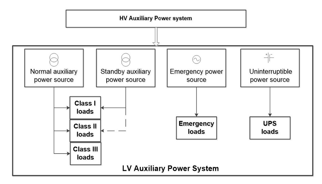
Figure 1 - Sketch map of LV AC auxiliary power sources
The wiring of LV AC auxiliary power systems or the way of supplying loads is determined by the selected voltage class, the way of acquiring power sources and the design principles of LV AC auxiliary power systems. The typical wiring scheme is “power center-motor control center”, namely, “PC-MCC” wiring scheme. This scheme, characterised by simple wiring and reliable equipment, can ensure service reliability, is shown in Figure 2. The PC is characterised by a single bus with sections, and each section is fed by two power sources: #1 auxiliary transformer and #3 LV auxiliary transformer. #1 supplies normal power while #3 is standby to the PC bus section. The power source of MCC of large scale units can be either led from two PC buses or two sections of the same PC bus. This wiring type is very common in 125-300 MW thermal power plants.
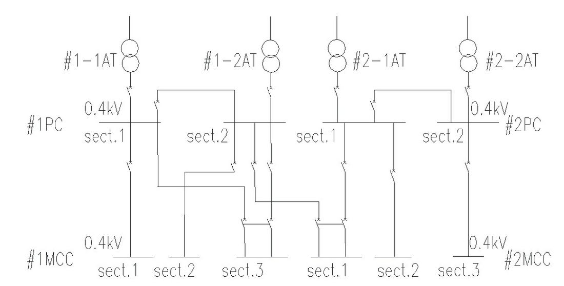
Figure 2 - Wiring of Power Center - Motor Control Center (PC-MCC)
The design subjects and requirements of LV AC auxiliary power systems in substations and converter are similar to those in power plants. The voltage class of a substation is also the same as that of LV distribution for industrial and civil use. The amount of the LV auxiliary equipment in converter stations is larger than that in substations as the converter station has a larger area. A double level radial distribution network is thus adopted, which is the same as that of the power plant [2].
Summary
This Technical Brochure provides readers a comprehensive guide of the design, installation, operation and maintenance of LV AC auxiliary power systems with the hope that it will become a useful reference for those who try to get a better understanding of auxiliary power systems.
The authors have worked hard to compile from disparate sources relevant information and a key point to highlight is the general lack of guidance on this topic, which is the same as in the case of CIGRE TB 777. This reiterates the reason for establishing the Working Group CIGRE B3.42 to develop this Technical Brochure.
The final point to raise is the relatively poor information on auxiliary power systems. One of the main conclusions in this TB is, there needs to be some consolidated effort in the standards organisations to produce some basic guidance surrounding the design and operation of these critical systems, and as a minimum utilisation of this document and its sister on LV DC auxiliary power supplies to provide best practice and points of reference.
- [1] [a]GE Industrial Power System Data Book, General Electric Company, 1978 [b]DL/T 5153, Technical Code For The Design Of Auxiliary Power System Fo Fossil-Fired Power Plant,(industrial standard published in China)
- [2] Operation Analysis and Study on Auxiliary Power System of HVDC Project, high voltage engineering, 2006,32(9):157-159, Xu Weigang, Liao Wenfeng, Gu Shuyang

Other Technical Brochures