Fast Electromagnetic Transient Simulation Methods and Prospects of High-frequency Isolated Power Electronics Transformers
With the increasing uptake of distributed renewable energy and low-carbon technologies (e.g. energy storage and electric vehicle), the conventional AC distribution network is transferring to hybrid AC/DC or pure DC. Power electronics transformers (PETs), also known as solid-state transformers, are multifunctional of integrating distributed generation, regulating bidirectional power flow, and achieving grid interconnection, reactive power compensation, harmonic control, etc. Therefore, PETs can serve as key interfaces for energy conversion in future distribution networks.
At present, a number of medium- and low-voltage distribution networks using PETs have commissioned in China, such as the Xiaoertai substation in Zhangbei and Tangjia Bay three-terminal DC distribution network in Zhuhai. The off-line and real-time electromagnetic transient (EMT) simulation studies are of great significance for system-level analysis and prototype development of PETs, which should be investigated timely.
by Jianzhong Xu, Yuhao Sun, Chenxiang Gao, Moke Feng, Chengyong Zhao and Gen Li
North China Electric Power University, China and Cardiff University, UK
Why do we need PETs?
In conventional distribution networks, the networks and links are connected through power transformers. In this case, inverters are needed to access various AC and DC loads. However, PETs can achieve flexible AC/DC conversion while realizing voltage level transformation, which eliminates the need for grid-connected inverters and therefore, simplifies system configurations. Comparing with conventional power transformers, the input and output waveforms and power flow of PETs can be regulated more flexibly, which can improve the power quality of the power grid. These benefits make PETs an enabler for future distribution networks.
Challenges of PET EMT simulations
A detailed EMT model of the PET would be suitable for the topology and control design for a single PET. If there are PETs in a complex network, the simulation burden of the whole system would be very heavy and the simulation speed may not be acceptable. Therefore, fast and accurate modeling of PETs is needed.
Detailed EMT model of the high-frequency isolated PET is based on discrete components in the simulation platform which is a complex structure and requires a lot of simulation resources. In contrast, the efficient modeling of modular multilevel converters (MMCs) proposed by the University of Manitoba is relatively mature and has been widely recognized and applied in commercial EMT simulation platforms [1]. Moreover, an accelerated modeling method for other complex multiport MMC submodules (SMs) has been developed in [2]. However, efficient and accurate algorithms for high-frequency isolation PETs are still under-researched because it faces the following challenges compared to efficient modeling of MMCs:
1. Complex power module structure
The configurations of PET power modules are complex and diverse. Specifically, they include the dual active bridge (DAB), single active bridge, cascaded H-bridge based DAB with AC port and multiple active bridge (MAB) composed of these power modules connected through multi-winding AC transformers. The PET used in the Xiaoertai project employs the MAB, as shown in Figure 1.
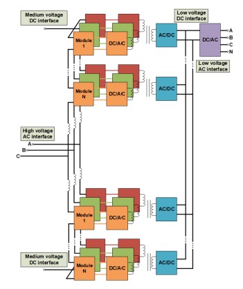
Figure 1 - Topology of the PET in the Xiaoertai Project
2. Various connection methods of power modules
Since the input and output ports of PETs may need to withstand high AC and/or DC voltages and currents, the PET power modules can be connected in multiple schemes, including input series output parallel (ISOP), input parallel output series, input series output series, input parallel output parallel and the combination of the above schemes. In Figure 1, the input terminals of the "three-to-one" quadruple active bridge (QAB) power modules are located at the upper and lower arms of the three phases.
3. High order Nodal admittance matrix
A single PET power module contains several power electronic switches and energy storage components, and thus consumes a large number of internal nodes. Although the MMC usually has larger number of modules than PET due to its higher voltage level, the PET may have similar number of nodes as well as the admittance matrix order. For example, as shown in Table 1, a detailed model of a three-phase MMC with 480 half-bridge SMs (HB-SMs) has almost the same number of nodes compared with the detailed model of the PET used in the Xiaoertai project which has 56 QABs.
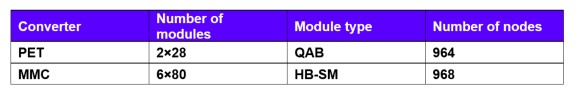
Table 1 - Nodes of PET and MMC
4. Requirement of small simulation time-step
Because of the high-frequency link (HFL) within the PET, to guarantee the accuracy of the phase shift control and power management of the PET, the simulation time-step needs to be reduced from 10-20 μs required by MMC to 1-5 μs. The comparison of the required time when simulating the same time duration of both MMC and PET is given in Table 2. It can be seen that although the PET has less components the computation burden is heavy like the MMC due the required small simulation time-step.
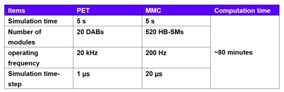
Table 2- Simulation time of PET and MMC
Efficient modeling of PET for EMT simulations
In line with the above four major challenges of the EMT modeling and simulation of PET, we have proposed a PET efficient modeling framework [3], [4] including "Accompanying circuit construction", "Internal node elimination" and "Converter equivalent circuit formation", as shown in Figure 2. Based on this framework, we have proposed three PET efficient models including "Transformer port decoupled model (EM1)", "High-frequency link decoupled model based on admittance equation preprocessing (EM2)" and "Port cascade based on admittance equation preprocessing (EM3)".
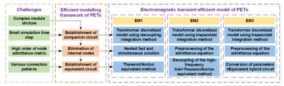
Figure 2 – PET efficient modeling framework
Simulation tests of the PET efficient models
The detailed model (DM) and three efficient models of a DAB based ISOP PET (modules N = 3, 5, 10, 20, 50, 100) are built in PSCAD/EMTDC to test their simulation time and speedup factor. In the simulations, the transformer frequency is 1 kHz and the simulation time step is 5 μs. A ground fault at the low-voltage DC bus is set at t = 0.6 s. Scenarios of start-up, power step-change and fault recovery are tested to verify the accuracy of the proposed models. The results are shown in Figure 3.
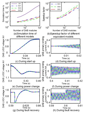
Figure 3 - Simulation results of different models
It can be seen from Figure 3 that the acceleration effect is EM2>EM1>EM3. When N = 100, all three models can achieve a speedup of 2 to 3 orders of magnitude. EM2 performs the preprocessing of the admittance equation and port decoupling in the formation of a single module equivalent circuit, therefore it has the best acceleration effect. Moreover, compared with the detailed model, the average relative errors of the external and internal behaviors of the models are all less than 3%.
Prospects for the research of PET EMT simulations
1. Multi-rate simulation based on time scale transformation
At present, most of the existing work of EMT simulation of PETs is based on the fixed-step simulation program. However, the EMT process of PET contains multiple time scales. The whole system can be divided into several subsystems according to the specific simulation requirements of the components and therefore, different time-steps can be selected to simulate the sub-networks. Based on the theory of time scale transformation, multi-rate simulation of the whole system can be realized.
2. Real-time simulation based on FPGA parallel computing
Since the equivalent circuits of PET modules are determined by their own internal structures and their firing pulses are independent, the module circuits can be solved in parallel. Also, once the equivalent circuit of the PET is solved, the modules can be grouped and superposed in parallel. Moreover, the inverse solution process of the voltage and current information of each module is also independent of each other. The above characteristics make it easy to realize the parallel calculation of the EMT efficient model of PETs. Therefore, it has excellent application prospects in real-time simulation platforms such as FPGA and RT-LAB.
- [1] J. Xu, D. Hui, S. Fan, A. M. Gole and C. Zhao, "Enhanced high-speed electromagnetic transient simulation of MMC-MTdc grid," Electr. Power and Energy Syst., pp.7-14, March 2016.
- [2] J. Xu, S. Fan, C. Zhao and A. M. Gole, "High-Speed EMT Modeling of MMCs With Arbitrary Multiport Submodule Structures Using Generalized Norton Equivalents," IEEE Trans. Power Del., vol. 33, no. 3, pp. 1299-1307, June 2018.
- [3] M. Feng, C. Gao, J. Ding, H. Ding, J. Xu and C. Zhao, "Hierarchical Modeling Scheme for High-Speed Electromagnetic Transient (EMT) Simulations of Power Electronic Transformers," IEEE Trans. Power Electron. (Early Access)
- [4] J. Xu, C. Gao, J. Ding, X. Shi, M. Feng and C. Zhao, "High-Speed Electromagnetic Transient (EMT) Equivalent Modelling of Power Electronic Transformers," IEEE Trans. Power Electron., vol. 36, no. 2, pp. 975-986, April 2021.
Suggested content