Transforming 3D substation design with engineering design automation
Over the past decade, utilities have increasingly relied on 3D design applications to perform physical design and electrical layout of substations, including both new and expansion projects. It is now time to rethink design processes and automate the engineering analysis required for substation design.
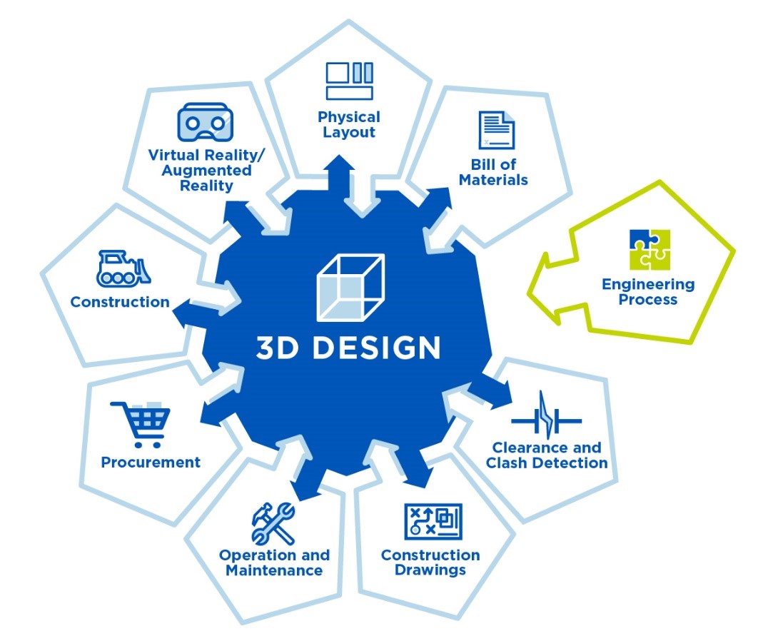
Consider that utilities today rely on model-based design programs for everything from automated drawings and bill of materials (BOM) creations to clearance checks and clash detections. By combining the completed 3D substation models with other emerging technologies, these programs have found ways to further leverage their value.
Paired with virtual reality (VR) technology, for example, a 3D model can be shared across disciplines, enabling others to visualize and experience the design and provide input. In other cases, augmented reality (AR) technologies can be used to overlay safety information or step-by-step maintenance instructions onto 3D models to support construction and maintenance activities. The value of model-based design grows, in short, when it is enriched with additional data.
By Paul Somboonyanon and Matt Lemke, Burns & McDonnell
Despite these successes and the promise of many more, the utility industry has seen little coordination thus far between the electrical designers who rely on model-based design and the other engineering disciplines that play significant roles in substation design.
The question is, why? The most obvious answer is that current model-based design applications are focused on a substation’s physical design and layout. They are not yet equipped to address the engineering analyses associated with civil and structural engineering.
Complicating matters is the fact that there is no common design software used for structural and civil engineering design. Site grading, structural design and foundation design each are completed using a different design application and process. Current limitations in model-based design software make it unfeasible to accommodate all the various applications used during the design process.
Many utilities’ in-house engineering design tools, including engineering math software and spreadsheets, also are not currently supported by model-based design applications. Civil and structural engineers, in short, speak a language that model-based design programs do not yet understand. The resulting gap is a weight on project success.
Consider the process for designing steel support structures for substation equipment. After completing their designs, electrical engineers typically provide equipment specifications and other data to the structural engineers who complete the structure and foundation design. The structural engineers use this data to calculate the structural loads that the supports must be able to carry. Next, they design the steel support structures and all their connections, followed by the foundation design. Finally, they prepare construction drawings.
Existing model-based design applications are only able to support that final step: construction drawing preparation. Any contributions these engineers make to a 3D substation model to reflect structural engineering analyses must be performed manually. If the manufacturer later reports that the equipment is heavier or larger than originally specified, the structure, foundation and connections must be redesigned. New specifications must be relayed to the structural engineers, the design processes repeated and the model updated accordingly. The manual iterations needed to integrate design changes in a project, from start to finish, are both time-consuming and error-prone.
The good news is that more efficient connections between physical design processes and structural analysis are possible. However, model-based design programs require more high-quality data points and tools to translate the data into a language these programs understand.
Solutions that allow the digital movement of data will not only allow structural analysis to be automatically updated in the physical layout, but also have the potential to reduce errors and costs.
Thinking differently about data
Although current model-based design software cannot support the civil and structural applications used in substation design, it can process data from these applications once it is digitally formatted in a way it can understand.
Some utilities already use building information modeling (BIM) software that contains tools they can use to restructure and digitize data-intensive engineering analysis so it can be connected to model-based design. Autodesk Revit with available plug-ins for RISA-3D, Autodesk Robot Analysis, SAP2000 or ETABS software suites is just one example.
It is also possible to import and export data using external tools such as Dynamo, Grasshopper, FME and UiPath, all of which support data integration. Tools like these can manipulate data and aid in design automation in different applications. They also make it possible to connect results from existing in-house design tools and other engineering applications with model-based design from all disciplines, including structural designs, steel connection and foundation designs, ground grid designs, and equipment selection.
In other words, the biggest thing standing in the way of better data integration is old habits.

Grabbing the brass ring: generative design
In addition to being incompatible with model-based design applications, manual engineering processes have another inherent limitation: They require a human to complete them.
When engineering analysis is digitally transformed, that limitation is removed and new doors open. Perhaps the most significant is the possibility for generative design and its promise of greater design optimization.
Today many structural engineering designs follow a parametric design approach — that is, design driven by parameters. Engineers begin by developing a set of design parameters based on the minimum design requirements in the applicable building code.
For example, engineers might define the design parameters for a foundation by its dimensions. If the design parameters call for a 6-foot-by-6-foot foundation, engineers will check the resulting design against code requirements. Presuming the design meets the code, they may — time permitting — check three to five other variations before proceeding to construction drawings.
Now consider a larger project with multiple foundations. Engineers may choose to design a dozen foundations to accommodate different settings. Depending on whether the final selection is driven by construction costs or the schedule, they may not have the time or budget to run more than three or four parameter variations on each set.
These examples point out the weaknesses in parametric design. While effective at meeting minimum design requirements, it rarely produces the most optimized design solutions. Because humans are performing the work, time does not permit all possibilities to be considered.
Generative design changes this, allowing engineers to explore many possibilities and achieve design optimization without exhausting their resources.
The generative design approach is based on a range of values set by engineers for each design parameter. Instead of a 6-foot-by-6-foot foundation, for example, the design parameters might call for a foundation that ranges from 4 feet to 9 feet in length and from 5 feet to 9 feet in width.
The ranges for all these variables are combined in generative design, providing exponentially more sets of parameters than is possible with parametric design. Consider again the foundation design, but with human limitations removed. By designating a range for each parameter, engineers might consider 500 different sets of parameters, compared to 50 or 60 possible through the single set points in parametric design.
In addition to analyzing each parameter to see if it meets code minimum design requirements, engineers using generative design also set an optimization rate for each parameter. That way, the process can identify the design option that is both most optimized and best meets project constraints.
But there is a catch: Manual engineering processes and data transfers won’t cut it. A generative design approach is only possible when engineering analyses are digitally integrated with a substation’s physical 3D design.
That is just one more reason why the time has come to bridge the gap between model-based substation design processes and engineering design automation.
For many utilities, all it takes is a change in mindset. By rethinking old processes and taking advantage of digital tools to move data, utilities can open the door to more optimized designs and savings in time and money.
About the authors
Paul Somboonyanon, Ph.D., SE, PE, P.Eng, is an associate structural engineer in the Transmission & Distribution Group at Burns & McDonnell. Recent assignments include development of workflows for model-based substation design using a BIM process.
Matt Lemke is a CAD section manager in the Transmission & Distribution Group at Burns & McDonnell. His experience in the drafting and design of overhead transmission line projects includes a focus on automation and design workflows.
Thumbnail credit: Josh Rose on Unsplash


