Measuring techniques and characteristics of fast and very fast transient overvoltages in substations and converter stations
In recent decades, the application of new power equipment and transmission technologies in power systems has made power girds much more complex than before. As a consequence, power equipment insulation systems are exposed to transient voltages with increasingly shorter rise-times and thus higher frequency components.
Convenor
(CN)
S. XIE
Secretary
(CN)
C. ZHUANG
L. KOCIS (CZ), F. WANG (CA), S. OKABE (JP), M. YANG (CN), Y. GONG (US), K. INAMI (JP), P. KANG (CN), F. ISSOURIBEHERE (AR), J. ARINOS TEIXEIRA JUNIOR (BR), G. SARCINELLI LUZ (BR), O.J. ROTHSTEIN (BR), B. FILIPOVIĆ GRČIĆ (HR), I. TANNEMAAT (NL), X. HAN (CN), G. BEHRMANN (CH), S. NILSSON (US), Y. LIU (CN), Z. MU (CN)
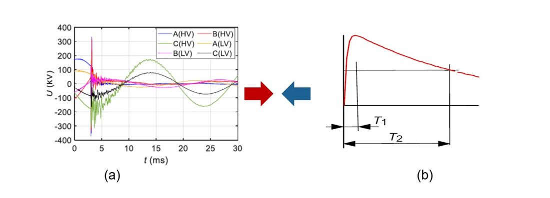
For most insulating materials, their insulation withstand levels and aging strongly depend on the waveform characteristics of the applied voltage. However, the insulation performance tests for almost all high-voltage power equipment are conducted using voltage waveforms specified in the various product-specific international standards (such as the standard lightning impulse voltage, the standard switching impulse voltage, etc.). However, the actual transient voltage waveforms which occur on site may differ substantially from the standard impulse voltages adopted in high-voltage tests (see Figure 1), and may thus pose an unpredictable risk of damage to the power equipment insulation [1].

Figure 1 - Figure (a) shows a typical measured lightning transient voltage. Figure (b) shows the standard lightning impulse voltage specified in existing high-voltage test standards
The presence of such transient voltages in the field with new and unaccounted for characteristics makes it necessary to review the applicability of existing high-voltage test standards and insulation coordination standards, especially for power grids operating newer and higher voltage grades along with ones equipped with a large number of new power equipment. Moreover, the transient voltages caused by grid faults contain much information on the occurrence and development of the faults which can be used in analyzing failure causes and locating the faults. Therefore, field measurements of the actual fast and very fast transient voltages are worthwhile and can benefit development of acceptable high-voltage dielectric test methods and economic insulation design schemes, as well as analyzing grid failure causes.
Fast and very fast transient voltages normally have very short front times (rise-times) and thus very wide frequency spectra. Front times can be shorter than several nanoseconds, resulting in bandwidths ranging from the power frequency up to 100 MHz. Meanwhile, the appearance of some transient voltages such as lightning transients or fault transients are unpredictable. Unfortunately, conventional voltage measuring equipment (such as capacitive voltage transformers, potential transformers etc.) typically found in substations are usually incapable of measuring fast and very fast transient voltages, due to their narrow bandwidths and low sampling rates.
The characteristics of fast and very fast transient voltages require measuring systems with ultra-high performance in field measurement. In recent years, some institutes, universities, and companies have developed several kinds of measuring systems to deal with fast and very fast transient voltages. Measurements of such transient voltages carried out in the field have helped researchers to understand the new overvoltage events, solve the corresponding insulation problems, and review the applicability of the existing high-voltage test and insulation coordination standards. However, concerning transient voltages in the existing power grid, there are still lots of questions unanswered. Meanwhile the application of new power equipment and new transmission technologies constantly produce new transient phenomena. Thus, there could be a long-term need for field measurement of transient voltages. As there are no relevant guides or standards, the researchers and engineers who carry out field measurements may face the following questions:
- How to choose suitable sensors, signal transmission techniques, and recording instruments to develop the measuring system according to the situations they face,
- How to specify the performance requirements of the measuring system to ensure the accuracy of measured transient voltages,
- How to test the performance of the measuring system to confirm if they have met the expectations, and how to calibrate them?
- When doing field measurements, what test lay-outs are suitable, and what are some typical results obtained by other researchers and engineers?
Content of the Technical Brochure
In order to provide a base-line reference for those concerned with transient voltages in the field and to provide a technical basis for the possible future preparation of a technical standard, this technical brochure will address the following aspects:
- Review the classifications, definitions, and characteristics of transient voltages along with the basic concepts of transient measurement in existing standards.
- Introduce the basic principle, key technical points, advantages and disadvantages as well as performance of multiple sensing techniques; present the appropriate signal transmission and recording techniques.
- Propose performance requirements, testing methods for measuring systems, and provide guidance for setting performance parameters such as measurement accuracy, bandwidth, scale factors, etc.
- Provide examples of field measurement case studies for the references of the users.
- Provide guidance to assist users dealing with the attendant electromagnetic compatibility (EMC) problems encountered when carrying out VFT measurements (proper grounding and shielding, avoiding damage to sensitive equipment, etc.).
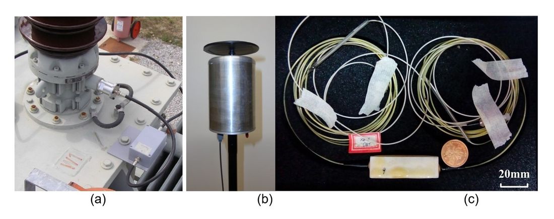
The survey results of this Technical Brochure show that the bushing sensor and non-contact electric field sensor are the main techniques to measure the switching transient voltages in AIS. And a well-developed bushing sensor generally has an upper frequency limit of 1~2 MHz. [2]
The non-contact sensor based on traditional electrotechnical technique generally has an upper frequency limit of several MHz [3], while optic-based non-contact measurement technique is enabled with a bandwidth from DC to higher than 100 MHz. [4]

Figure 2 - Figure (a) shows a bushing sensor. Figure (b) shows an electrotechnical electric field sensor. Figure (c) shows an optical electric field sensor
Embedded electrode sensor and porthole sensor generally works for transient voltage measurements in GIS. Embedded electrode sensor has an upper frequency limit higher than 10MHz [5]. Nevertheless, the porthole sensor appears more frequently in measuring transient voltage in GIS. A well-developed porthole sensor generally has a lower frequency limit of several mHz and higher frequency limit beyond 100 MHz [6].
To ensure the measurement accuracy, a series of performance requirements of measuring system were specified. An uncertainty lower than 10% is acceptable for the field measurement system. The 3 dB and 1 dB lower frequency limits of the measuring system are proposed to be lower than 10 Hz and 50 Hz, respectively. In terms of upper frequency limits, recommended values for SFO, FFO and VFFO are 20 kHz, 2 MHz and 100 MHz, respectively. The sampling rate should not be lower than 20 times of reciprocal of front time or lower than 4 times of the highest frequency of oscillating component.
In order to guide users to test their measuring system, the test methods for bandwidth and scale factor were introduced in this document as well. The frequency sweep method is preferred for determining the frequency characteristics of the measurement system with an upper frequency limit lower than several MHz. For VFFO measuring system, the determination of two bandwidth borders can be done by the step response and DC response or long-tail impulse response, respectively. The methods in calibrating scale factor should be chosen carefully according to the layout, sensing principle and the dependence on the main power equipment of the measuring system.
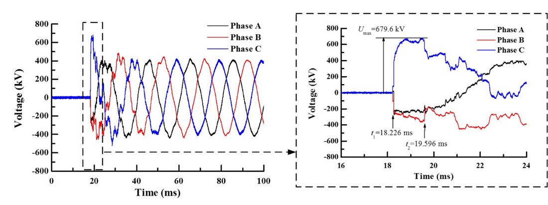
The measurement results imply that the fastest switching transient voltage in AIS is featured by a front time of hundreds of nanoseconds. As a practical example, a typical field measured switching transient voltage is shown in Figure 3. In UHV AC project, measured long-front transient waveform offers an important reference for proposing insulation withstand tests under long-front impulse voltage for UHV AC power equipment.

Figure 3 - Transient voltage during switching on a long no-load transmission line
The actual lightning transient voltage waveforms imposed on the substation power equipment are mainly featured by attenuation waveform of bipolar oscillation with a front time from the order of microsecond to 0.1 millisecond, which are highly different from current standard lightning impulse voltage waveform. Thus, discussions are raised by the difference on the appropriate standard lightning impulse voltage waveform widely used in high-voltage tests.
The field measurement results show that, the fastest VFFO has a front time of only several nanoseconds and a high-frequency component is beyond 50 MHz. The actual VFFO waveform is affected by the switching operation phase, residual charge, busbar length, circuit stray capacitance, etc. It also confirms the positive effect of the circuit damping resistor in suppressing VFFO magnitude.
Conclusion
This Technical Brochure could help users design and develop their own measuring system for transient voltages, ensure accuracy and reproducibility of the field measurements by different groups, and better understand fast and very-fast transient phenomena and their effects in power grids.
- [1] S. Okabe, J. Takami, T. Tsuboi, and et al. Discussion on standard waveform in the lightning impulse voltage test. IEEE Trans. on Dielectrics and Electrical Insulation, 2013, 20(1): 141-156.
- [2] [a] B. Filipovic-Grcic, B. Jurisic, S. Keitoue, I. Murat, D. Filipovic-Grcic and A. Zupan, “Analysis of Overvoltages on Power Transformer Recorded by Transient Overvoltage Monitoring System,” in 5th International CIGRE Colloquium "Transformer Research and Asset Management", Opatija, Croatia, 2019. [b] Lubomir Kocis. FTO and VFTO – Generation and measurement techniques during decades in EGU HV LAB. C4.45 working group report, 2017.
- [3] [a] R. Bianchi, B. Barbieri, G. Mayer, F. Issouribehere. Voltage transient measurements using electric field sensors and ATP modelling of a 500 kV GIS station. CIGRE Paris Session 2018, C4-205. [b] Wenting Li, Zhaozhi Long, Shaobo Liu, et al. Development of a spherical space transient electric field measuring instrument based on wireless transmission. China Measurement and Test, 2019, 45(4): 85-91.
- [4] Xie, S. J., Su S. C., Zhang Y., and et al. Field measurement of lightning transient voltage in substations using optical electric field sensor. CIGRE Paris Session 2018, C4-208
- [5] S. Okabe, M. Kan, T. Kouno. Analysis of surges measured at 550 kV substations. IEEE Trans. on Power delivery, 1991, 6(4): 1462-1468.
- [6] Yue Gongchang, Liu Weidong, Chen Weijiang, and et al. Measurement methods of very fast transient overvoltage in gas insulated switchgear with complete process. Proceeding of the CSEE, 2011, 31(31): 18-27.


