After Laying Tests on AC and DC Cable Systems with New Technologies
Over the past years, the development in equipment available for on-site commissioning and maintenance testing of HV & EHV cable systems has progressed, such that test sets are now available for testing of long lengths of HV cable using modernized version of resonant test sets, Very Low Frequency (VLF) test sets or Damped AC (DAC) test sets. As a result, CIGRE formed working group B1.38 to investigate the application of HV & EHV cable systems testing using new technologies. The findings and associated recommendations have been outlined in Technical Brochure 841.
Convenor
(CA)
M. FENGER
Secretary
(UK)
S. WILLIAMS
X. BALZA (ES), J. BUSBY (US), Q. DE CLERCK (BE), S. FRANCHI-BONONI (IT), E. GULSKI (SZ), K. GUSTAFSSON (SE), C.E. HILLESUND (NO), S. D. MIKKELSEN (DK), P. MOHAUPT (AT), R. PLATH (DE), T. DUPLESS (SA), E. PULTRUM (NL), H. YOUNES (US), M. JEROENSE, SAG Advisor (SE)
Corresponding Members: R.J. DENSLEY (CA), K. LEEBURN (SA), F. PETZOLD (DE)
It should be noted, the Scope of Work for the Working Group was large and also involved researching, in detail, material science aspects of cable testing using near power frequency (NPF), Very Low Frequency (VLF) and Damped AC (DAC) stresses. The findings are complex and not possible to summarize in a meaningful manner in short form within this article, however, TB 841 contains detailed discussions with respect to the application of NPF, VLF and DAC voltage sources for HV & EHV cable systems.
Scope and outline of the work
The main purpose of WG B1.38 was to:
- Examine the present status, including limitations, of available voltage sources capable of testing HV & EHV AC & DC Transmission Cable Systems.
- Investigate practical limitations, risks and test burdens related to the different test methods.
- Consider technical aspects involved to establish test parameters such as voltage level, test durations (number of excitations for damped AC) and frequency ranges for different voltage sources (this includes evaluating the voltage levels in IEC 60840 and IEC 62067 for AC Resonant Testing).
- Recommend what work needs to be done if the technical background is not available.
- Evaluate and provide recommendations for use if the technical background/data is available.
- Address the merits of different diagnostic tests.
To achieve these terms of reference, three separate Task Force Groups were formed:
Task Force 1, titled “Test Experiences & Test Database”, was formed with the objective of gathering commissioning and maintenance test experiences from around the world allowing for a test database to be established to help assess existing test practices and also the effectiveness of testing. A survey template was developed and sent to CIGRE membership countries for input and a database was developed . The database was mined for existing test practices and aided in the development of test recommendations (Chapter 4 of TB 841).
Task Force 2, titled “Equipment Survey” was formed with the objective of gathering information on the currently available voltage sources and their capability of testing HV & EHV AC & DC Transmission Cable Systems (Chapter 3.8 of TB 841).
Task Force 3, titled “Literature Survey” was formed with the objective of carrying out a large study of published documentation (standards, transaction papers, journal papers, technical magazine papers, conference & symposium papers) on research performed on testing of HV systems and HV system components using near power frequency, very low frequency and Damped AC voltage sources. The survey undertook a large body of work which helped identify risks and test burdens related to the different voltages sources when applied to DC and AC cable systems (Chapter 3.9). As well, the literature survey helped identify knowledge gaps and areas where further research/investigations are required (Chapter 3.10). For the literature survey, only existing standards and guides as well as, largely, peer-reviewed non-commercial publications have been considered.
The Technical Brochure falls in to three main parts: The first part, Chapters 2 and 3, provide an introduction to and discussion of Cable Systems and Testing of Cable Systems. In particular, Chapter 2 contrasts the differences between MV and HV/EHV systems which is necessary for understanding the discussions in Chapter 3.9 “Consideration for Testing” and Chapter 3.10 “Existing Knowledge Gaps”.
Chapter 3 “Testing of Cable Systems” describe and discuss testing of cable systems with DC, Damped AC, VLF and NPF voltage sources. Each voltage source is discussed and described in Chapters 3.1 through 3.7. Chapter 3.8 “Equipment Capabilities” outlines the capabilities of existing testing equipment as per mid-2019. Chapter 3 is concluded in Chapters 3.9 “Considerations for Testing” and 3.10 “Existing Knowledge Gaps”. Chapter 3.9 discusses, in technical detail, considerations for electrical testing of cable systems using various voltage sources from the point of view of withstand testing and partial discharge measurements. Chapter 3.10 identifies and discusses existing knowledge gaps as per mid-2019.
The second part of the Technical Brochure, Chapter 4, outlines existing test experiences. The data is current as of the end of 2016.
The third and final part of the Technical Brochure, Chapter 5, contains test recommendations for commissioning and maintenance (asset condition assessment) of new and field aged AC XLPE, EPR and oil filled cables as well as DC XLPE and MIND cables. Care has been taken to avoid inconsistencies between this Technical Brochure and existing standards and recommendations.
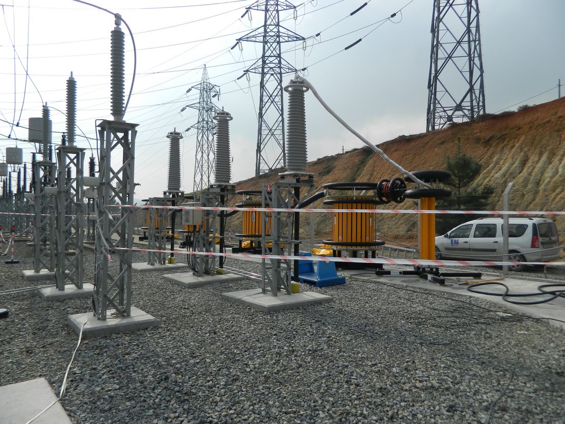
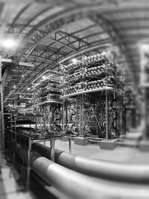
Figure 1 - Photo of four reactor parallel configuration for testing a long hv cable feeder
Considerations for testing
Chapter 3.9 is technically complex and requires the subject matter described and discussed in Chapter 2 as well as Chapters 3.1 through 3.8 to be understood.
Chapter 3.9 explains and discusses the influence of voltage wave shape on (1) withstand testing and (2) partial discharge activity. This also includes a discussion on voltage magnitude and applied duration. With respect to Partial Discharge behaviour, the chapter contains a discussion on voltage shape (magnitude, frequency and stability), on PD magnitude and PD intensity, Partial Discharge Inception Voltage (PDIV) and Partial Discharge Extinction Voltage (PDEV), and issues related to false positives and false negative for PD measurements.
It should be noted, as pointed in out in Chapter 3.9, that PD sensitivity in a classic sense is independent of the voltage source but rather a consequence of the cable system, the coupling between the PD sensor and the cable system as well as the capabilities of the PD monitor. Guidance is provided for when single ended, double ended and distributed PD measurements should be used with TB 841 referencing the recommendations made in CIGRE TB 728.
Lastly, Chapter 3.10 identifies existing knowledge gaps. These were identified largely via a literature study of peer reviewed literature and also by taking in to account actual test experiences. The Working Group agreed that the knowledge gaps as of 2021 were:
- Maximum allowable electrical stresses at interfaces when testing solid dielectric cables with VLF.
- Electrical Tree Inception & Tree Growth for High Stress Cable Systems (EHV): most technical studies of electrical tree inception and tree growth were performed on systems having stresses equivalent to MV and HV cable systems but not to EHV cable systems.
- Space Charge formation and behaviour at dielectric interfaces: most space charge behaviour studies relevant to the Work look at bulk dielectric effects or at effects at the conductor dielectric interface but not at dielectric interfaces such as, for instance, at joints and terminations.
- Little Experience with Maintenance Testing of HV & EHV solid dielectric and EPR cable systems with NPF.
- Little Experience with Commissioning and Maintenance Testing of HV & EHV solid dielectric and EPR cable systems with VLF.
- Moderate experience with maintenance testing of HV & EHV solid dielectric and EPR cable with DAC.
- Testing of, Solid Dielectric HVDC systems: the literature survey found little data related to testing of aged solid dielectric HVDC systems.
As such, Chapter 3.10 directly delivers on one of the Terms of Reference of the Working Group.
Test experiences
As part of the Scope of Work, data on commissioning and maintenance testing experiences with DC, NPF, VLF and DAC was collected. The breakdown of the data collected is as per Table 1 below. For all voltage sources, the data obtained for this analysis ranges from 1997 to end the end of 2016.
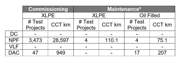
Table 1 - Test experience data base break down (* more than 5 years old)
As can be seen, for NPF and DAC for HV cable systems the data base can be considered statistically significant and thus allows for mining of data in terms of test experiences and for comparison of test outcomes between different voltage shapes. For the test experiences gathered for EHV cable systems with DAC the subset of data was not considered sufficiently large to be statistically significant.
Note, the WG did receive some data for VLF tests performed on HV cable system but upon further analysis it was clear that for voltage magnitudes, peak magnitudes were referenced and, as such the voltage applied was in some cases below and in other cases near to the rated-line-to ground voltage of the cable system, thus not considered for analysis.
The approach taken for comparing test experience between NPF and DAC was to compare Non-Pass-Rates for terminations and joints for commissioning testing (Table 4 of TB 841). For a full discussion of the test experiences, please refer to Chapter 4 of TB.
Test Recommendations & Guides
Chapter 5 contains recommendations for commissioning and maintenance testing of XLPE, EPR and Oil Filled Paper AC system, as well as recommendations for Commissioning Testing of DC Cable Systems. The chapter also provides recommendations for diagnostic testing of new cable systems with Damped AC.
As a background for the recommendations derived by the WG, the chapter describes the purpose of a commissioning test, an after-repair test of a new cable system and a maintenance test of a field-aged cable system.
For XLPE and EPR cable systems, the WG’s recommendations are in line with IEC 60840 and IEC 62067. However, following test practices and test experiences for the past 5-6 years (see Appendix C of TB 841), for 220kV – 400kV cable system it is recommended to test at 1.7U0 for 60 minutes.
Based on the literature survey and, thus, on research performed (contrasting PD behaviour between NPF and VLF) it was possible to derive recommendations for VLF withstand testing for both sinusoidal and cosine-rectangular VLF. Multiple studies show relation of breakdown voltage between NPF and VLF (for similar defects) for new cable systems for a factor 1.7. But following the principle of caution the scale factor applied for sinusoidal VLF relative to NPF was 1.5. For cosine-rectangular VLF an additional factor of Ö2 (1.41) is applied. As such the peak stress is similar between sinusoidal VLF and cosine-rectangular VLF. For EHV cables, no recommendations were made for commissioning testing using VLF as further studies are required (FSR). Specifically, if applying the necessary scale factor for VLF to existing test NPF withstand voltages for EHV cable systems, the maximum stress limit of 30 kV/mm at interfaces will be breached.
The test recommendations for commissioning testing with NPF and VLF voltage sources is as per Table 2 (Table 5 in TB 841).
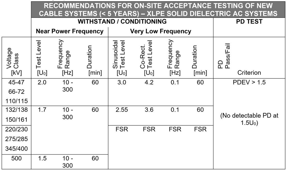
Table 2 - Recommendations for after-laying testing of new XLPE cable systems
As well, separate guidelines for diagnostic testing of new XLPE and EPR cables with Damped AC were developed – see Table 3.
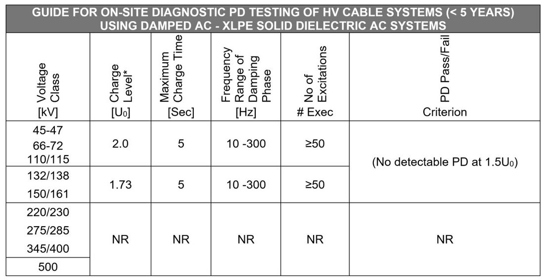
Table 3 - Guide for damped ac diagnostic testing of HV cable systems less than 5 years of age
As a result of the literature survey and research related to applying stresses at frequencies below 0.1 Hz, following a principle of caution, the work group recommends that when making use of Damped AC the charge time should be limited to 5 seconds or less and, as well, alternating excitations (shots) of negative and positive polarity voltage should be applied. Thus, a voltage shape as per Figure 2.
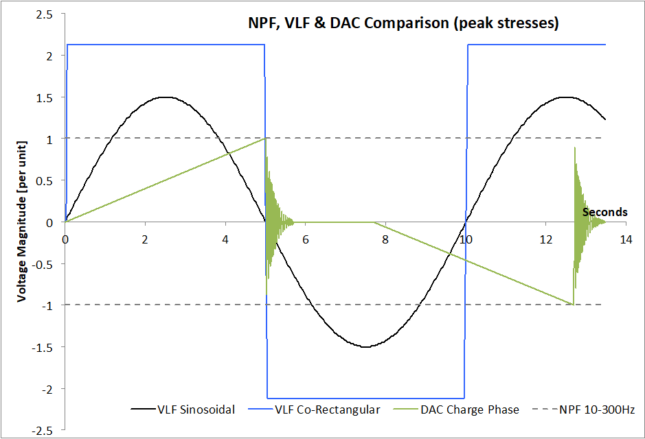
Figure 2 - Comparison of voltage waveforms for commisisoning testing
Note, based on the literature survey and associated research performed (similar to VLF) recommendations for the use of DAC for EHV cables was not developed as, based on the present methodology this would cause electrical stresses at interfaces to exceed 30 kV/mm.
For maintenance test recommendations for XLPE, EPR and Oil Filled Paper cable with NPF, VLF and DAC voltage sources, please refer to Chapter 5 of TB 841. Note, for testing of oil filled cable systems the recommendations provided relate to DC stresses. However, based on test experiences submitted and also based on the literature study the Working Group did provide guidance for AC testing of Oil Filled Paper AC Systems; The guidance provided by the Working Group is AC voltage be applied but the peak of the applied AC voltage shall not exceed the recommended DC test voltage. The Working Group made note that applying AC stresses allows for PD measurements and potentially Tand measurements to be performed on Oil Filled Paper cables.
Conclusions
The terms of reference for the Working Group were as follows:
- Examine the present status, including limitations of available voltage sources capable of testing HV & EHV AC & DC Transmission Cable Systems.
- Investigate practical limitations, risks and test burdens related to the different test methods.
- Technical considerations involved to establish test parameters such as voltage level, test durations (number of excitations for damped AC) and frequency ranges for different voltage sources (this includes evaluating the voltage levels in IEC 60840 and IEC 62067 for AC Resonant Testing).
- Recommend what work needs to be done if the technical background is not available.
- If the technical background/data is available, then evaluate and provide recommendations for use.
- The merits of different diagnostic tests will also be addressed.
To achieve these terms of reference, three separate Task Force Groups were formed:
Task Force 1, titled “Test Experiences & Test Database”, was formed with the objective of gathering commissioning and maintenance test experiences from around the world allowing for a test database to be established to help assess existing test practices and also the effectiveness of testing.
Task Force 2, titled “Equipment Survey” was formed with the objective of gathering information on the currently available voltage sources and their capability of testing HV & EHV AC & DC Transmission Cable Systems. The Survey was updated in 2019 (Chapter 3.8).
Task Force 3, titled “Literature Survey” was formed with the objective of carrying out a study of published documentation (standards, transaction papers, journal papers, technical magazine papers, conference & symposium papers) on research performed on testing of HV systems and HV system components using near power frequency, very low frequency and Damped AC voltage sources.
As a result of the work performed in the various task forces, recommendations for commissioning and maintenance testing of HV and EHV cable systems were developed (Chapter 5). From the test experiences gathered in Task Force 1 it was clear that too little broad experience exists with VLF testing of HV & EHV cable systems such that it could lead to solid conclusions in the spirit of CIGRE. Therefore, in developing recommendations for VLF testing of HV & EHV cable systems, guidance has been taken from MV testing practices and from research performed in the field also at higher electric fields. In developing the recommendations and, in some cases, guides, for commissioning and maintenance testing the working group has strived to remain focused on technical aspects and, where risks and rewards have had to been assessed, the assessment has been from a technical point of view taking into account what is practically possible testing wise. Where grey areas may have existed for development of recommended voltage levels and durations for the various voltage sources the principle of caution has been adapted. This was done to ensure the recommendations provided to not cause damage to the cable system under test.
References
Technical Brochure 841 reflects an intensive and critical reading of scientific literature coming from research and experiences. The list of reference below gives an essential glance of them, worth to be highlighted in the present article. For a full list of references, please refer to the Technical Brochure.
- L.A. Dissado & J.C. Fothergill, “Electrical Degradation and Breakdown in Polymers”, IEE Publications, Peter Peregrinus Ltd. London, United Kingdom
- Ying Li, Masataka Yasuda and Tatsuo Takada, “Pulsed Electroacoustic Method for Measurement of Charge Accumulation in Solid Dielectrics”, IEEE Transactions on Dielectric and Electrical. Insulation, vol.1, no. 2, 1994, pp.188-195
- Takada T., “Acoustic and Optical Methods for Measuring Electric Charge Distributions in Dielectrics,” IEEE Transactions on Dielectric and Electrical. Insulation, vol.6, no. 5, 1999, pp.519–547
- M. Fu, G. Chen and J. C. Fothergill, “The Influence of Residue on Space Charge Accumulation in Purposely Modified Thick Plaque XLPE Sample for DC Application”
- Y. Li and T.Takada, ”Progress in Space Charge Measurements of Solid Insulating Materials in Japan”, IEEE Electrical Insulation Magazine, September/October 1994-Vol.10, No.5
- L. A. Dissado, G. Mazzanti and G. C. Montanari, “The Role of Trapped Space Charges in the Electrical Aging of Insulating Materials”, IEEE Trans on Dielectrics and Electrical Insulation, Vol 4, No. 5, pp. 496-506, 1997
- L. A. Dissado, C. Laurent, G. C. Montanari and P. H. F. Morshuis, “Demonstrating a Threshold for Trapped Space Charge Accumulation in Solid Dielectrics under dc Field”, ”, IEEE Trans on Dielectrics and Electrical Insulation, Vol 12, No. 3, pp. 612-620, 2005
- W. Wang, D. Jiang, W. Dong, Z. Ning, J. Xiong , G. Du, “The Effect of Charge Rate on Space Charge Accumulation in Damped Alternating Current (DAC) Testing for Power Cable” , ICHEV 2018
- S. A. Boggs, “Theory of a Defect-tolerant Dielectric System”, IEEE Trans on Electrical Insulation, Vol 28, No. 3, pp. 365-371, 1993
- C. G. Garton, “Dielectric Loss in Thin Films of Insulating Liquids”, Journal IEE, Vol 88, PE II No. 1, February 1941
- Densley, J., “Ageing Mechanisms and Diagnostics for Power Cables—An Overview,” IEEE Electrical Insulation Magazine, January/February 2001—Vol. 17, No. 1
- A. Pedersen, G. C. Crichton and I. W. McAllister, “The Theory and Measurement of Partial Discharge Transients”, IEEE Trans on Dielectrics and Electrical Insulation, Vol 26, No. 3, pp. 487-497, 1991
- Gockenbach, E. and Hauschild, W., “The selection of the frequency range for HV on-site testing of extruded cable systems,” IEEE Electrical Insulation Magazine 16 (2000), pp.11–16
- M. Fenger, “Experiences with Commissioning Testing of HV & EHV Cable Systems: The Influence of Voltage Level and Duration for Identifying Life Limiting Defects”, Conference Record of the 2012 IEEE International Symposium on Electrical Insulation (ISEI), June 2012
- Proff. D. Pepper, “Grundlagenuntersuchung zum Teilentladungsverhalten in kunststoffisolierten Mittelspannungskabeln bei Prüfspannungen mit variabler Frequenz und Kurvenform”, Ph.D Thesis,
- Dr. R. Bach, “Untersuchungen zur Vor-Ort-Prüfung von Mittelspannungskabeln mittels Spannungen unterschiedlivher Form”, Ph. D. Thesis, Elektrotechnik – Technische Universität Berlin, September 1993
- Dr. G. Schiller, “Das Durchschlagverhalten von vernetztem Polyethylen (VPE) bei unterschiedlichen Spannungsformen und Vorbeanspruchungen”, Ph. D. Thesis, Fakultät für Maschinenwesen der Universität Hannover.
- Plath, R., “Oscillating Voltages,” als Prüfspannung zur Vor-Ort-Prüfung und TE-Messung kunststoffisolierter Kabel, Ph.D. Thesis, Verlag Dr. Köster, Berlin, Germany, 1994
- P. Mohaupt and A. Bergman, "A New Concept for Test Equipment for Testing Large HV and UHV Cables On-site," CIGRE 2010 France
- S. Bergman and A. Bergman, "New Reference Measurement System for Calibration of VLF High Voltage," IEEE Trans. Instrum. Meas., vol. 60, no. 7, pp. 2422-2426, July 2011.
- W. Kemmetmüller and A. Kugi. (2011) Mathematical Modelling and Analysis of a DRT-VLF High Voltage Test Generator. e&i – Elektrotechnik und Informationstechnik.
- D. Götz, F. Petzold, and H. T. Putter, "Investigations on a Combined Resonance/VLF HV Test System – Partial Discharge (PD) characteristics at VLF and DAC voltages," presented at the CMD, Jeju, South-Korea, 2014.
- H. Auclair, W. Boone and M.S. Papadopulos, “Development of a New After Laying Test Method for High Voltage Power Cable Systems”, CIGRE SC 21, CIGRE 1988 Session, 21-06
- C. Aucourt, W. Boone, W. Kalkner, R.D. Naybour and F. Ombello “Recommendations for a new After Laying Test Method for High Voltage Extruded Cable Systems”, CIGRE 1990 Session, 21-105
- Farneti, F., Ombello, F., Bertani, E., Mosca, W., “Generation of Oscillating Waves for After-laying Test of HV Extruded Cable Links,” CIGRE 1990 Session, 26th Aug.–1st Sept., 1990, Paper 21-110
- Farneti, F., Ombello, F., Bertani, E., Mosca, W., “After Laying Test of Extruded Insulation Cable Links.” 6th ISH, Paper No. 45.02, New Orleans, U.S.A. August, 1989
- Seitz, P. P., Quak, B., Gulski, E., Smit, J. J., Cichecki, P., de Vries, F., Petzold, F., “Novel Method for On-site Testing and Diagnosis of Transmission Cables Up to 250 kV,” Proceedings Jicable '07. 7th Intern.Conf. Insulated Power Cables, Versailles, France, Paper 16, 2007
- K. Rehtmeier, P. Mohaupt, V. Bergmann, W. Kalkner and G. Voigt “New Studies on PD Measurements on MV Cable Systems at 50Hz and Sinusoidal 0.1 Hz (VLF) Test Voltage”, 19th International Conference on Electricity Distribution, 19th International Conference on Electricity Distribution, Paper 0627, Vienna 2007
- W. McDermid & J. C. Bromley, “Condition Assessment of Service Aged XLPE Distribution Cable”, Proceedings of the 2001 Electrical Insulation Conference and Electrical Manufacturing and Coil Winding Conference, October 2001
- X. Feng, Q. Xiong, A. Gattozzi, G. C. Montanari, P. Seri, and R. Hebner “Cable Commissioning and Diagnostic Tests: The Effect of Voltage Supply Frequency on Partial Discharge Behaviour", 12th IEEE International Conference on the Properties and Applications of Dielectric Materials - Xi'an - China
- G. Mazzanti, J. Castellon, G. Chen, J. C. Fothergill, M. Fu, N. Hozumi, J. H. Lee, J. Li, M. Marzinotto, F. Mausheth, P. Morshuis, C. Reed, I. Troia, A. Tzimas and K. Wu “The Insulation of HVDC Extruded Cable System Joints. Part 1: Review of Materials, Design and Testing Procedure”, IEEE Trans on Dielectrics and Electrical Insulation, Vol 26, No. 3, pp. 964-972, 1991
- E. Pultrum, S.A.M. Verhoeven, “Testing of Extruded Cables: experience in Type Testing, PQ Testing and Test After Installation. What do we learn from it?”, CIGRE 2004, paper B1-104
- M. Wild; S. Tenbohlen; E. Gulski; R. Jongen, Basic aspects of partial discharge on-site testing of long length transmission power cables, IEEE Transactions on Dielectrics and Electrical Insulation, 2017 , Volume: 24 , Issue: 2, Pages: 1077 – 1087
- P.P. Seitz, B. Quak, E. Gulski, M. Wild, F. de Vries, Long lengths transmission power cables on-site testing up to 500 kV by damped AC voltages, Jicable 2015
- J. Smit, M. van Riet, B. Staarink, Non-destructive after laying test with PD localization, JiCable 2019, paper D3-4
- R. Bodega, et al., "PD recurrence in cavities at different energizing methods," in IEEE Transactions on Instrumentation and Measurement, vol. 53, no. 2, pp. 251-258, April 2004.

Other Technical Brochures