Feasibility study for assessment of lab losses measurement of VSC valves
As transmission losses are directly related to the investment and operational costs, they are one of the most important factors for High Voltage Direct Current (HVDC) project evaluation. For Voltage Source Converters (VSC), valve losses are the largest part of the total converter station losses and therefore the determination and evaluation of the VSC valve losses becomes highly important.
Presently, the losses of VSC valves are determined based on the calculation methods of IEC 62751-1 and -2. The calculation method requires detailed information such as the parameters of semiconductor devices, VSC valve design characteristics and operating modes, which are usually not directly available to the HVDC system purchaser/user, who consequently finds it difficult to evaluate the calculated losses results.
The purpose of this WG is to perform a feasibility study to assess laboratory loss measurement methods on VSC valves for loss calculation evaluation purposes and to make recommendations considering the pros and cons of such measurement methods versus the methods in IEC 62751.
Convenor
(DE)
C. RATHKE
Secretary
(NL)
Y. FU
S. BØDAL (NO), C. DAVIDSON (GB), J. DORN (DE), Q. LI (CN), J. LIGER (FR), R. ONISHI (JP), C. PLET (NL), B. SHENG (SE), Z. SONG (GB), Y. ZHOU (CN)
Technical Brochure 844 starts with a general description of losses in VSC HVDC converter valves, the origins of different losses in components, the dependency of the losses on different operating modes, as well as special aspects of different designs. This is followed by a summary of the current practice for valve losses determination, including the modelling of the semiconductor parameters and then by a discussion on how the transparency of the overall calculation process can be enhanced. As the main study results of the WG B4.75, an evaluation of the existing methods to measure losses is provided. This is complemented by an overview of the operation conditions and additional aspects for losses measurement (such as commercial aspects) that need to be taken into account. In the last part, the results are summarized and recommendations for application of losses measurement are given, which can be used as guidance for the introduction of losses measurements in the operational type tests of VSC valves.
Generic illustration of the various components of valve losses
A generic illustration of the various components of valve losses components and how they are split between different cooling media (liquid coolant and valve hall air) is shown in Figure 1. It should be noted that the distribution of losses depends strongly on the valve design (e.g. which components have been bolted onto the liquid-cooled heat sink), and on the converter operating point (e.g. full load or no load). In most converters all losses are eventually evacuated to the ambient air, although in offshore converters a substantial part may also be evacuated to the sea water.
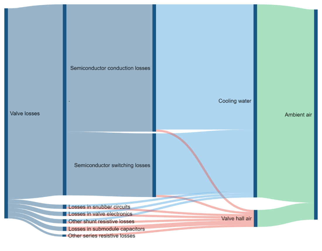
Figure 1 - Generic illustration of valve losses components and cooling
Current practice for valve losses determination
Today’s practice is to determine valve losses by combination of device/component losses measurement and calculation according to IEC 62751. The main steps are:
- Manufacturer and their supply chain carry out routine and characterisation tests on key valve components
- Manufacturer simulates complete VSC station to find the valve voltage, valve current, switching instants and other relevant operating parameters
- Manufacturer calculates valve losses based on steps 1 and 2
- Manufacturer writes report summarising results of loss calculation and passes it to purchaser
By using data from datasheets, previous projects, previous R&D tests and simulation, a loss calculation result can be obtained during the bidding process and used as the basis of a guaranteed loss figure forming part of the bid. If necessary, the loss calculations can later be repeated at the project execution stage, using data from the routine tests performed on the components actually supplied for the project. The overall process is illustrated in Figure 2 and Figure 3 below and the sources of information typically used at the bid stage and project execution stage are shown in the Table 1 below.
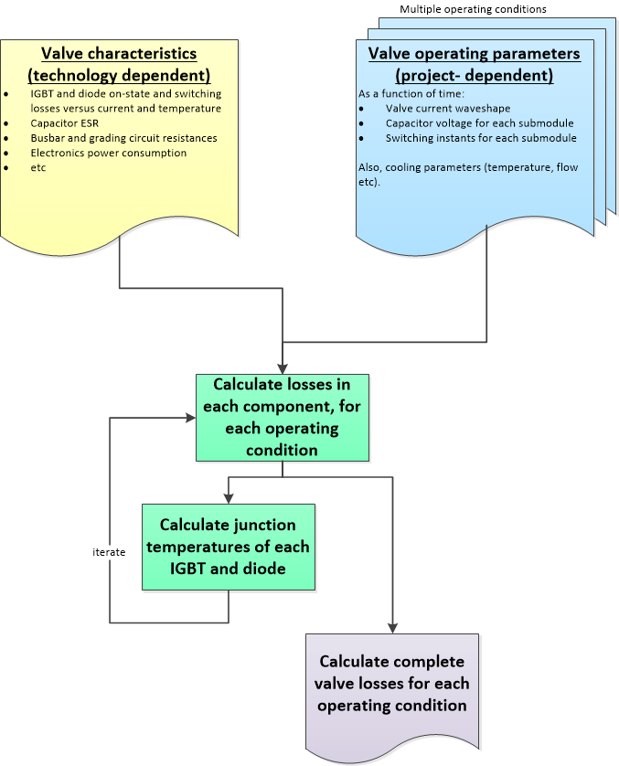
Figure 2 - Summary of overall process

Figure 3 - Losses determination process of a real project
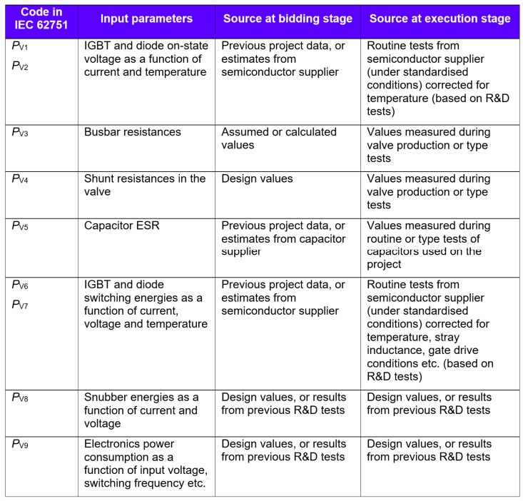
Table 1 - Typical sources of valve characteristic data at different stages in the project lifecycle
However, there are some deficiencies in the standard. In particular, this method requires a very detailed simulation describing every instantaneous current in every semiconductor component in every simulation step, so the calculation workload is beyond the human capability and an automatic program is required. The two main areas of deficiency are:
- the lack of standardisation of how the semiconductor parameters should be modelled as a function of current, temperature etc.; and
- the lack of transparency of the overall simulation process for the purchaser.
Generic illustration of lab valve level or valve section losses measurement locations
A generic operational valve type test set-up typically consists of a test object, which is coupled to a test source by means of a load impedance (usually an inductor). The test source is powered by a DC power supply which supplies the power losses in the entire test set-up. The test object and test source require liquid cooling which can be supplied from the same or separate cooling systems, depending on the choice of test source. The valve level or valve section losses measurements can be performed using the same operational valve type test set-up. The losses measurement locations are illustrated in the Figure 4 below.
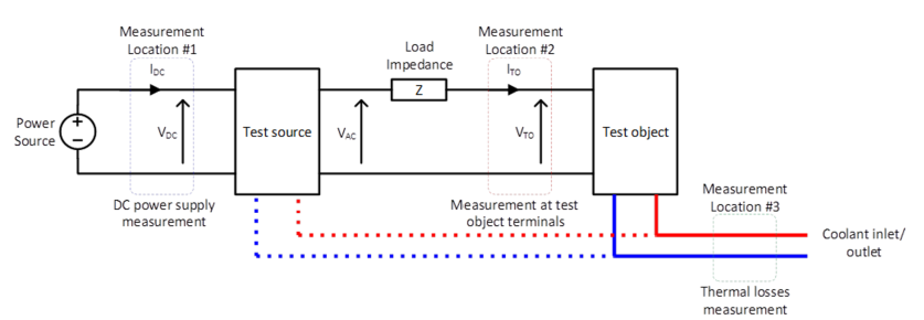
Figure 4 - Generic valve level or valve section losses measurement test set-up
Overview of reviewed losses measurement methods
Device level loss measurement and components measurement as described in section 4.2 of the brochure have been used in HVDC. They are the basis for losses calculations according to IEC 62751 – 1/2. Other possible valve losses measurement methods are discussed in section 4 of the brochure and summarized in the following Table 2.
| Methods | Section in BT 844 | Object | What is included | Advantages | Disadvantages |
|---|---|---|---|---|---|
Site measurement Pin-Pout | 4.4 | on one converter | Whole station losses | Most complete measurement | - Not exclusively for valves; |
Site electrical measurement | 4.4.1 | on BtB converters | Whole station losses | Very complete and more accurate than above | - Need additional primary equipment for reconfiguration |
Site thermal measurement: ∆T x flow rate | 4.4.2 | on one converter | All liquid coolant- evacuated converter valves losses | - Simple | - Inaccurate |
Lab electrical measurement, Measuring directly losses fed to circuit. | 4.3.1.2.2a | on single valve level or valve section | Losses of single valve level or valve section, including load reactor | High accuracy for test circuit | - Dependent on the test setup used, current & voltage waveforms may not be fully representative |
Lab electrical measurement, Measuring voltage & current of test object | 4.3.1.2.2b | on single valve level or valve section | Losses of single valve level or valve section, without load reactor | Completeness good | - Dependent on the test setup used, current & voltage waveforms may not be fully representative |
Lab thermal measurement, without calorimetric chamber for losses into air | 4.3.2. | On single valve level or valve section | Only liquid coolant-evacuated valve level or section losses | Simple | - Dependent on the test setup used, current & voltage waveforms may not be fully representative |
Lab thermal measurement, With calorimetric chamber for losses into air
| 4.3.2. | On single valve level or valve section | Only liquid coolant-evacuated valve level or section losses | Very complete | - Dependent on the test setup used, current & voltage waveforms may not be fully representative |
Conclusion
The conclusion of the Working Group B4.75 is that the laboratory measurement of valve losses is feasible, although the level of accuracy achievable is still quite poor. The general recommendation therefore is that the laboratory measurement should become a standard part of the operational type tests of the VSC valves, such that in the coming years greater industry experience can be gained in this area. However, it is not recommended that the measured valve losses are used as part of the financial evaluation criteria for the HVDC project until there is a good industry experience and consensus over what should be a realistically achievable level of measurement uncertainty.


