Recommendations for testing DC extruded cable systems for power transmission at a rated voltage up to and including 800 kV
In 2012 Technical Brochure 496 “Recommendations for Testing DC Extruded Cable Systems for Power Transmission at a Rated Voltage up to 500 kV” was issued by Study Committee B1. This document followed the recommendations for testing of high voltage DC extruded cable systems published in the previous Technical Brochure 219. The recommendation was recognised by a large and relevant technical community and has become the reference for the wider community. Meanwhile, IEC published its first standard for HVDC cables IEC 62895 “High voltage direct current (HVDC) power transmission - Cables with extruded insulation and their accessories for rated voltages up to 320 kV for land applications - Test methods and requirements”.
Convenor
(IT)
S. FRANCHI BONONI
Secretary
(IT)
D. PIETRIBIASI
A.C. SARTIEAUX (BE), R. SVOMA (UK), A. ABBASI (SE), Y. TANAKA (JP), F. FÄLTH (SE), R. KING (UK), R. GASPARI (NO), S. WILLIAMS (UK), C. SZCZEPANSKI (BE), R. ZHANG DONGPING (DE), J. MATALLANA (NO), Q. EYSSAUTIER (NO), P. MIREBEAU (FR), C. FROHNE (replaced) (DE), Y. CORLU (FR), M. TALEB (replaced) (FR), A. PELIZZONI (IT)
Corresponding Members: H. ORTON (CA), L. SU KIL (KR), J. GAO (CN), J. CHAEKYUN (KR), M. FU (CN)
Objectives of the Technical Brochure
The large number of projects and the quick development needed by the industry to match the demand of always more performing HVDC systems requires commonly shared and agreed testing method to speed up the time to market of technology solutions.
In 2017 it was decided by Study Committee B1 to launch the new Working Group B1.62 to prepare recommendations for testing DC extruded cables systems at a rated voltage up to 800 kV. The decision was motivated by the fact that commercially available HVDC extruded systems above 500 kV were emerging. In fact, at the time of preparing this recommendation there was laboratory experience on cable systems at voltages up to and including 640 kV and operating experience was already at 400 kV, while contracts were awarded at a voltage level up to 525 kV. A further increase in voltage level is to be expected and this recommendation will therefore cover voltages up to 800 kV.
The emergence of new grid configurations (point-to-point, radial and meshed) is introducing new types of overvoltages (commonly referred to as Transient Overvoltages, TOVs) and the standard switching and lightning impulse wave shapes might not cover typical voltage stresses anymore. Thanks to the interface with JWG B4/B1/C4.62 the new waveshapes were evaluated and new testing methods are now included in this Technical Brochure.
Scope / Methodology
This document recommends a series of tests on extruded cables for DC power transmission systems (land or submarine cables with their accessories in fixed installations) up to and including 800 kV. The “extruded” insulation materials covered by this recommendation include thermoplastic polyolefins, mixtures of thermoplastic polyolefins, crosslinked polyolefins, mixtures thereof, and rubber-like materials. The materials maybe filled (e.g. with minerals or nano-particles) or unfilled.
The requirements have been differentiated as a function of the cable design and performance:
- Cables of voltage ≤ 400kV designed with an average stress ≤ 20 kV/mm, named HVDC in the TB
- Cables of voltage > 400kV or cables designed with an average stress > 20 kV/mm named EHVDC in this brochure
HVDC cables are of well-established technology, the requirements are the same as in TB 496, description of the tests has been improved when some uncertainty was detected.
EHVDC cables are of new technology and submitted to higher electric stresses. Additional tests have been introduced to assess their performance, namely:
- Thermal stability test
- Sample tests such as by product content in the case of XLPE
To comply with long link and converters technology requirements, new tests have been introduced. They can be applied to both HVDC and EHVDC:
- Transient overvoltage test
- Test of the screen insulation and sectionalisation of accessories.
Structure and Content of the Technical Brochure
Structure
Being a pre-standardisation document, the Technical Brochure is arranged as an international standard, it lists the proposed tests and performance requirements. This aims to ease its technical input to standardisation bodies. When necessary, the rationale that leads to the test(s) selection and performance requirement is detailed, especially when they are new as compared to TB 496.
Chapter 1 - Introduction
Introduction to the Technical Brochure gives its historical background in CIGRE B1 and the state of the art in the laboratories and in the market. The general content of the document is described, specially comparing TB 496 to the Brochure content.
The definition of the different tests corpus (Development tests, type tests, prequalifiquation tests, thermal stability tests, ...) is given as well as the definition of test objects, test voltages, thermal cable design parameters, thermal conditions for tests.
Chapter 2 - Qualification of a cable system
The following scope of tests is required for full qualification of a cable system:
Test | HVDC | EHVDC |
Prequalification Test or within its range of approval | X | X |
Type Test or within its range of approval | X | X |
Thermal Stability Test or within its range of approval | - | X |
Thermal stability testing of EHVDC cables has been included due to the increased electrical stress associated with EHVDC cable systems. Thermal stability is not required for HVDC cable systems.
Prequalification and Type Tests differs depending on the type of HVDC converter (Line Commutated Converter LCC or Voltage Source Converter VSC) that feeds the cable system.
Chapter 3 - Development tests
The manufacturer should complete all analysis and development testing prior to commencing the Prequalification test. The precise nature and extent of development work and analyses are left to the discretion of the manufacturer, but there is a list of recommended items to address:
- dielectric evaluation of the insulation system: resistivity, breakdown strength, space charge behaviour;
- long term stability: varying electric stress, temperature and environmental conditions;
- sensitivity to expected variations in cable dimensions, material composition and process conditions;
- electric stress distribution within the cable system insulation for a range of typical installation and loading conditions.
Chapter 4 - Prequalification tests
The prequalification tests are made before supplying on a general commercial basis a type of cable system, to demonstrate satisfactory long-term performance of the complete cable system. The test scope is different depending on the application type
It is a one-year test where the cable system is successively submitted to high dielectric and thermal stresses.
Thermal Load Cycles - High Load - Polarity Reversal (case of LCC qualification) - Zero Load - Superimposed Impulse Test
Chapter 5 - Type tests
Type Tests are performed before supplying on a commercial basis a type of cable system. All components of the cable system (cable and accessories) must be subjected to Type Testing.
Type Tests consist of two parts:
- Electrical Type Tests
- Non Electrical Type Tests
Electrical Type Tests are the same as in TB 496. They have been extended to submarine cables. They consist in mechanical preconditioning, load cycles under voltage, superimposed (to DC voltage) lightning and switching impulses. Also, due to the installation of long land cable links, screen insulation tests have been added (case of joints and accessories with screen interruption).
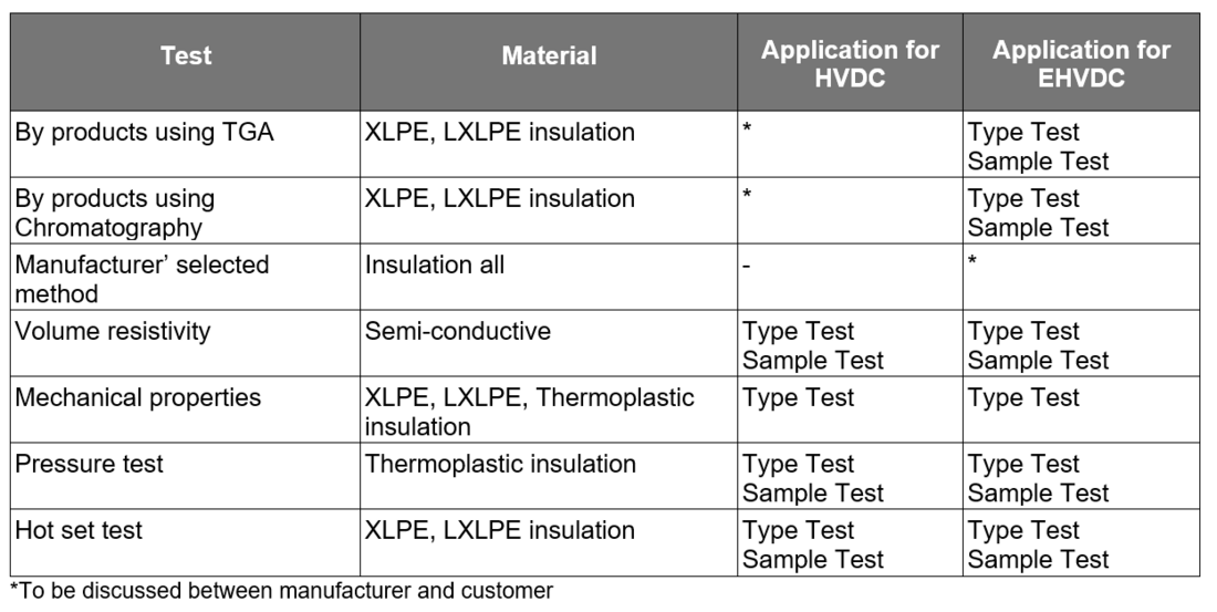
Non Electrical Type Tests have been extended vs. TB 496 to address the stronger requirements of EHVDC cable systems, and new tests have been added to characterise the new materials: thermoplastic and LXLPE.
They include the measurement of By Products Content on insulation material, Pressure Test on thermoplastic insulation materials, Hot Set Tests requirements for LXLPE.
Chapter 6 - Thermal stability test
A Thermal Stability Test (TST) is introduced to demonstrate the thermal stability of the cable and to highlight, if present, the possibility of an undesirable thermal run-away of the proposed solution.
Generally thermal run-away occurs when dielectric losses lead to an increase of local temperatures and a positive feedback occurs leading to an unstable situation that leads to an uncontrolled and catastrophic temperature increase.
During the thermal stability test the temperature increase of the test sample will be compared to the thermal behavior of a reference cable, where dielectric losses do not occur since the electrical field is negligible, to check whether the thermal behavior significatively differs among the two objects.
The TST Test procedure requires the test object and the reference loop to be heated up, with no voltage applied, until the reference cable conductor has steadily reached the desired max conductor temperature Tcond,max, the heating current shall therefore be maintained for the duration of the test; the test voltage of 1,45 Uo is then applied to the test object.
By monitoring the difference in temperature between the sheaths of the test object and of the reference loop it is possible to determine if thermal instability occurs.
Possibilities of extending the observation period are given in the TB, furthermore, rules to repeat the test with different conditions is provided in the TB as well.
Chapter 7 - Extension of qualification test
The Extension of Qualification Test (EQT) is introduced to verify the long-term performance of a previously qualified cable system when substantial changes are implemented. Accessories of different design/type can be inserted in the test loop for an EQT.
EQT is performed on a length of cable and a minimum of one accessory of each type, the test sequences have been established with the same philosophy selected for PQ and TT with a common duration of 82 days.
The same philosophy, examination procedures and success criteria applied to PQ and TT have been selected for the EQT.
Chapter 8 - Routine tests
Routine tests are made to demonstrate the integrity of the delivery lengths and accessories.
The WG has introduced several changes to the routine tests described in TB 496:
- Every delivery length of cable shall be submitted to DC test, and an AC test at a voltage to be agreed between manufacturer and customer. As a guidance, the maximum Laplace field stress associated with AC test voltage could be 20kV/mm for a duration of 30 minutes for HVDC cables and 23kV/mm for a duration of 60 minutes for EHVDC cables. It is recommended to perform the AC test before the DC test for safety reasons linked to the polarization of the insulation after the DC test.
- If required for the particular contract or order, the oversheath may be subjected to the routine electrical test specified in IEC 60229.
- A Time Domain Reflectometry (TDR) measurement could be performed for engineering information.
- The main insulation of prefabricated accessories shall undergo DC voltage routine tests; an AC test combined with PD measurement is also recommended. The test voltage is selected so as to obtain stresses at least the same as those on the component in a complete accessory when subjected to the cable AC test voltages.
Chapter 9 - Sample tests
Sample tests are tests made by the manufacturer on samples of complete cable or components taken from a complete cable or accessory, at a specified frequency, to verify that the finished product meets the specified requirements.
The sample tests for HVDC cables are basically the same as the ones selected and described in TB 496, but specific tests to LXLPE and thermoplastic insulation have been added.
Sample tests for EHVDC cables include all tests for HVDC cables plus by-product content.

Chapter 10 - Guide for the selection of test procedures in case of changes in a qualified cable system
This chapter is intended as a guide to reduce the time to market and the overall qualification cost of improvements by taking into account expected innovations in cable technology, following the philosophy introduced for HVAC cable systems by TB 303. A system approach is applied, even if the changes to be considered are based on components. Each component change requires that the tests are completed on the whole cable system.
50 modifications are addressed. Changes in cable conductor, insulation system (material and process), sheath, general design; joint material, main insulation, screen insulation, general design; factory joint process; termination materials and general design are evaluated. In each case a series of tests is recommended so that the change in the qualified cable system keeps it qualified for the same Tcond,max, Tmax and, if applicable
Tmin as the reference cable system.
In addition, two events have been evaluated: the case of different insulation compounds cleanliness grades, and the case of an interface joint i.e. a joint between two different qualified extruded cable systems.
Chapter 11 - After installation tests
After installation tests are made to demonstrate the integrity of the cable system as installed. They consist in a high voltage test of the main insulation, a voltage test of the screen insulation, and when appropriate, an optional Time Domain Reflectometry fingerprint of the wave propagation in the cable system.
chapter 12 - Overvoltage special temporary tests
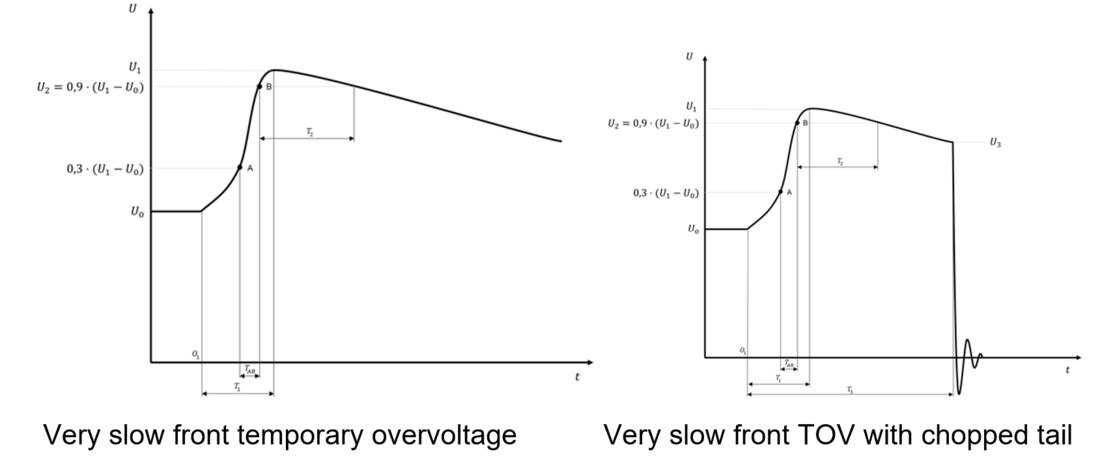
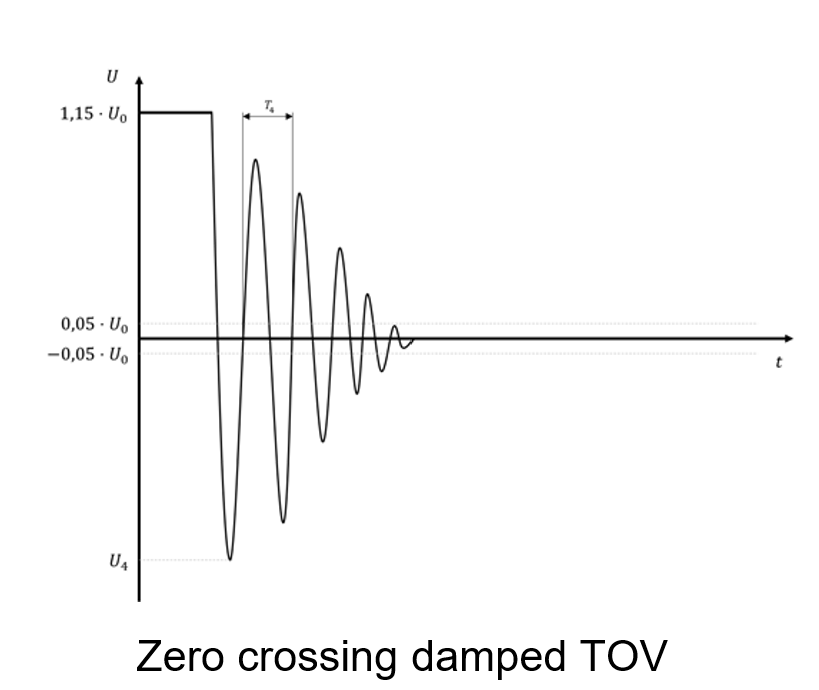
According to the work of CIGRE JWG B4/B1/C4.73, two new overvoltages can be experienced on HVDC cable systems on top of conventional lightning and switching impulses: very slow front overvoltages with same polarity to actual DC voltage and oscillating overvoltages with opposite polarity peaks to actual DC voltage. The latter occurs along the faulty cable during the cable discharge process. For the first, two fault types, phase-to-ground faults on the AC side and DC pole-to-ground faults on the DC side, were found to generate overvoltages leading to the highest peak values. From the parameter study it was concluded that occurring amplitudes are typically higher for the DC pole-to-ground faults and it is sufficient to focus on pole-to-ground faults for addressing the TOV behaviour of HVDC cables. The typical envelope of overvoltage shapes studied by CIGRE JWG B4/B1/C4.73 have been considered for the definition of the test parameters.
The intention of the tests is to verify that these special conditions together with the cable system design give acceptable results. As these types of overvoltages are related to fault conditions and their number is expected to be limited during system lifetime, the tests are intended only to investigate the system limits; therefore, the test values (namely voltage, time, and number of applied overvoltages) shall not be considered as design parameters for insulation coordination interface between Converter and Cable suppliers, which can be instead better technically argumented by the cable system manufacturer.
Three Temporary Overvoltage Tests are defined in the brochure:


In each case, the range of validity, the test procedure and requirement, the test set up are described.

Example of test set up for very slow front temporary overvoltage – blocking capacitor configuration
Conclusion
This Technical Brochure is a pre-standardisation document which recommends a series of tests on extruded cables systems for DC power transmission (land or submarine cables with their accessories in fixed installations) up to and including 800 kV. The “extruded” insulation materials covered by this recommendation include thermoplastic polyolefins, mixtures of thermoplastic polyolefins, crosslinked polyolefins, mixtures thereof, and rubber-like materials. The materials may be filled (e.g. with minerals or nano-particles) or unfilled.
At the time of preparing this recommendation there was laboratory experience on cable systems at rated voltages up to and including 640 kV, but operating experience was limited to 400 kV. Contracts had been awarded at a voltage level up to 525 kV. A further increase in voltage level is to be expected and this recommendation therefore covers voltages up to 800 kV. However, it is important to emphasise that the lack of operational experience above 400 kV and the limited number of tests at higher voltage levels represents an uncertainty in the preparation of this recommendation. Consequently, any relevant knowledge that emerges from increased testing and/or service experience at higher voltages may necessitate revisions of this recommendation in the future.


