Guidance on high-speed testing of turbo generator rotors
Engineers responsible for generator maintenance are often posed with the difficult question of whether to send the rotor off-site for high-speed balancing and testing or not. It is generally considered that by doing so is the lower risk option, however there can be substantial operational and financial pressures against doing so. This guide aims to provide operators with information required to help them make informed decisions as to whether to carry out high speed testing of generator rotors following repair or maintenance. The practice varies substantially across the world and engineers can be presented with difficult decisions to make under financial pressure.
Members
Convenor
(UK)
B. ADAMS
B. FENTON (US), B. MARCUSO (US), N. SMIT (NZ), B. O’SULLIVAN (EI), G. CSABA (SE), J. PORTER (UK), G. YAN (CN), H. SHIMADA (JP), B. MOORE (US), S. MITCHELL (UK), V. FERNABUT (FR), K. MIYAIKE (JP)
During the manufacture of high-speed turbine generators, the rotors undergo a number of tests to prove their integrity, both mechanically and electrically, from standstill to running speed and overspeed as well as from ‘cold’ to operating temperature, to ensure that the rotor does not exhibit high vibrations which may limit its operation in service. The following tests are typically carried out to prove that:
- The components of the rotor have the mechanical integrity to operate within the full speed range expected in normal operation
- The vibration levels of the rotor are acceptable through its run up, at rated speed and overspeed.
- The rotor is thermally stable, i.e., the vibration levels stay within acceptable levels as the rotor heats up, and, that the thermal stability is repeatable.
- The integrity of the insulation is maintained throughout the speed range, i.e., there are no rotor ground faults, and no inter-turn insulation defects.
These tests are carried out at the factory to prove the equipment is within requirements and limit the risk of operational issues at the plant. The worst-case scenario is that a severe mechanical defect would cause destruction of the rotor at site, causing catastrophic damage. This is a very rare occurrence in modern times, more likely is that a problem may occur at site which causes high vibrations, either requiring the generator rotor to be returned to a facility for correction, or for operational limits to be imposed. This work is usually referred to simply as “balancing” and there are relatively few facilities around the world capable of such work on large turbogenerators.
Testing is expensive and may add months to an outage program. It is common for engineers to face pressure to reduce outage timescales and cost, and to consider whether high speed testing of the rotor is necessary. Furthermore, the rotor is a costly strategic spare part, and the operator will want to have it ready to be used on site as required. A working group was set up in order to explore these issues to help users of generators make a better, informed decision as to whether they should opt to carry out high speed testing or not.
Scope and Methodology
The Working Group investigated the following:
- The scope of work which would require high-speed testing
- The availability of high-speed testing facilities
- Any guidance already in existence on this subject
- OEM guidance.
- 3rd party service provider’s guidance.
- The risk of introducing issues following work
- The risk remaining if high speed testing is not carried out
- Ways in which the risk could be mitigated.
The Working Group produced a questionnaire. Operators, OEMs, independent testing organisations and consultants were invited to share their experiences with generator rotor issues, what tests they would normally specify, and what problems they had experienced. The collected information was assessed and used to create a guide. However, it should be noted that the majority of responses came from European operators where it is an accepted practice to carry out high speed testing.
A risk matrix was created showing work carried out and relative risk if high speed testing is omitted from the work scope.
Description of the TB
The Technical Brochure provides detailed information on how generator rotors are constructed to assist the reader with understanding how and where various issues may develop.
Generator Rotors
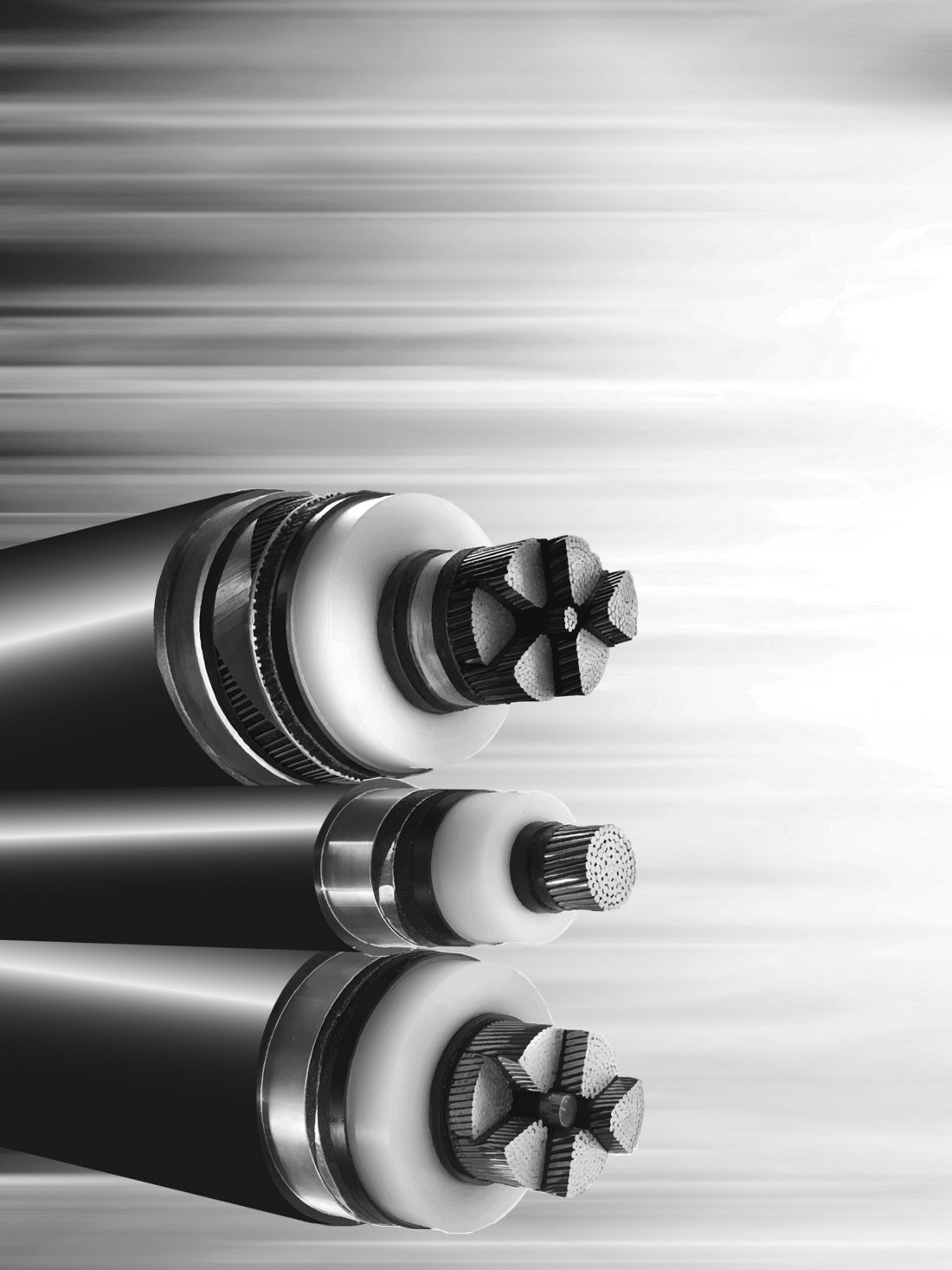
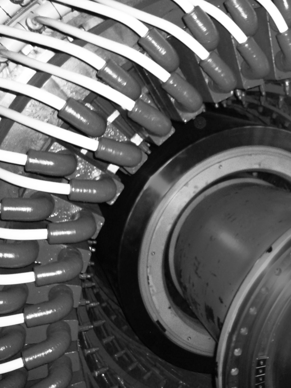
The rotor is the rotating component which is coupled (directly or indirectly) to the prime mover. The rotor is a high-speed component which carries DC current through coils wound into machined forged steel shaft. Slots are cut into the steel, within which strips of copper are inserted. These strips of copper are connected in series to form a large coil of many turns, which are insulated from each other (Figure 1 and 2). Applied current creates a magnetic field, which when spun by the turbine provides the excitation to the main armature coils within the generator stator to produce the output. Most conventional rotors for high output generators are 2-pole and will operate at the system frequency (3000 or 3600rpm) with some, notably most generators installed in nuclear plants, operating at half speed (1500 or 1800rpm), and can weigh up to several hundred tonnes.
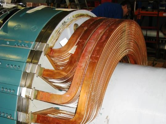
Figure 1 - Generator rotor endwinding with retaining ring
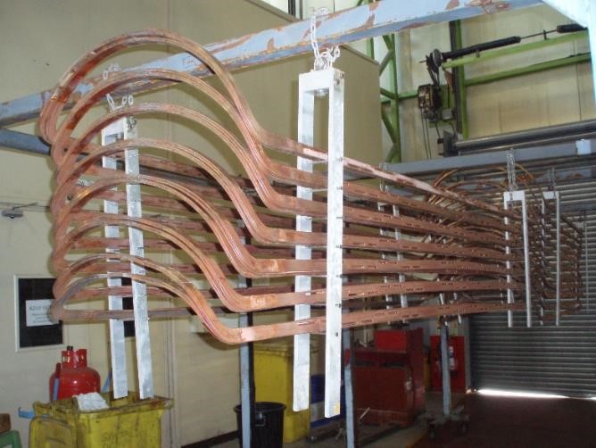
Figure 2 - Rotor coil removed from the forging removed
Potential issues and repairs
Potential issues with the rotor are addressed in chapter 3 from an electrical and mechanical point of view and examples are shown. Finally, the topic of transportation is considered. Maintenance and repair of rotors is highlighted in chapter 4. The technical brochure provides examples of what work might be carried out; from a small inspection or repair with the retaining rings left in situ, to a full rewind and replacement of the copper or replacement of retaining rings.
In rotors the voltage is generally low, in the order of a few hundred volts with just a few volts between individual turns. However, the high current will create a large amount of heat (over a megawatt of resistive heating created in larger generators). The major challenge for rotor insulation systems is the mechanical complications caused by several constraints:
- When operating at speed, the rotor needs to be finely balanced to prevent high vibrations.
- As the rotor heats up internal components can move through thermal expansion or can become trapped if their slip planes do not allow free movement.
- If there are any electrical shorts between the turns of the winding, the resistive heat created will not be evenly distributed throughout the rotor. If the rotor heats unevenly, thermal expansion of the steel will cause the rotor forging to bend slightly and result in higher-than-expected vibrations.
During the manufacture of high-speed turbine generators, the rotors undergo a number of tests to prove their integrity. Both mechanically and electrically, from standstill to running speed and overspeed, as well as from cold to hot, to ensure that the rotor does not produce high vibrations which may limit its operation in service.
Balance and high-speed testing
The most important part of the document, the balancing and high-speed testing, is addressed in chapter 5. Details are given of an example of the high-speed balance and testing program with details of the various mechanical and electrical tests usually expected to be carried out on the rotor.
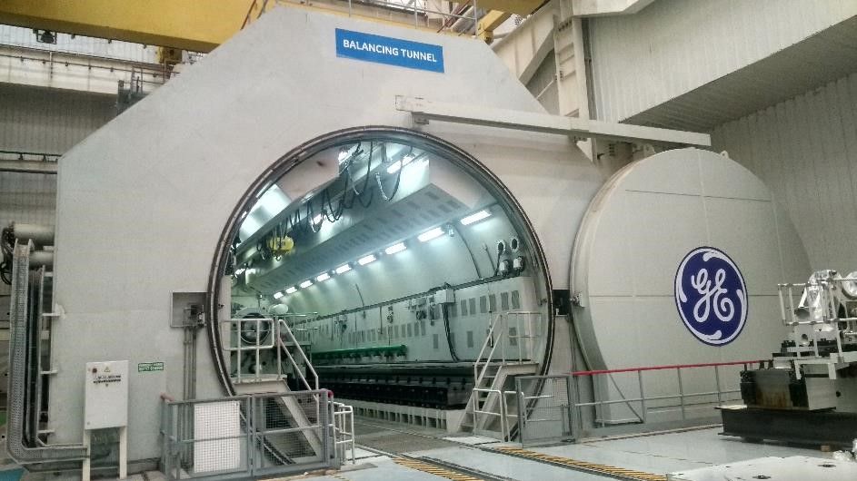
Figure 3 - Balance Facility (courtesy of GE)
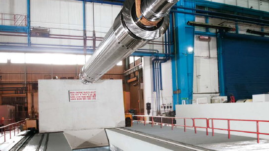
Figure 4 - Balance Facility (courtesy of Siemens)
Owner feedback
Chapter 6 provides the results of the survey. Most of the questionnaire respondents were from European large utility style operators who have had a great deal of experience on rewinding generator rotors. All would tend to require high speed testing as part of most work carried out on a generator rotor where possible. Unfortunately, no responses were received from any operators in Asia, Oceania or North America who could provide an alternative point of view.
With the information gathered, a map of large high speed balance facilities around the world was developed (figure 5). This task has been complicated by the changing nature of the energy business leading to consolidation and cost cuts reducing the amount of facilities in recent years.
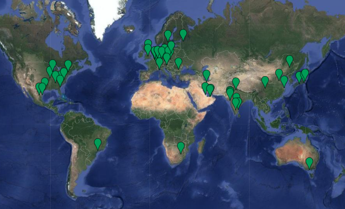
Figure 5 - Location of high-speed balance facilities
A risk matrix is provided with the aim of assisting the operators as to the varying levels of risk of not performing a high-speed test on rotors against examples of work scope.
Conclusions
The lowest risk option will usually be to have the rotor tested for electrical integrity and balance at a high-speed balance facility.
High speed balancing and overspeed testing offers several benefits including checking the mechanical integrity of the equipment to operate at speed, ensure that the rotor is balanced and remains stable throughout the operational envelope of the generator and to check the electrical integrity at speed.
Due to the relatively difficult access to a balance facility, the potential for transport complications (distance, handling, and customs implications), and the cost of and time taken for the work, there can be a compelling financial argument to avoid such tests.
If the decision is made not to carry out a high-speed balance along with electrical and overspeed testing, there are several potential problems which only be detected when operating at speed such as electrical faults or high vibration.
The guide provides a list of considerations and suggestions to assist the operator with their decision making, and how some of the risks may be mitigated.

Other Technical Brochures