Power Cable Rating Examples for Calculation Tool Verification
The International Electrotechnical Commission (IEC) publishes standards, which use formulae to calculate the current rating of a cable system. The current rating (often named “ampacity”) is the current which a cable can carry over a given time, such that the conductor attains – but does not exceed – the maximum operating temperature.
Members
Convenor
(NL)
F. DE WILD
Secretary
(NL)
J. VAN ROSSUM
G. ANDERS (CA), R. BASCOM (US), S. CRAY (UK), J. JOO (KR), W. KAMARA (CA), Q. KHUMALO (ZA), T. KVARTS (DK), F. LESUR (FR), A. LOTFI (NO), W. MOUTASSEM (US), J. PILGRIM (UK), K. PINKERT (DE), V. RIZOU (GR), O. THYRVIN (SE)
Corresponding Members
R. BENATO (IT), S. DAMBONE SESSA (IT), A. FALCONER (OM), Y. LIU (CN), F. GABRIEL OLIVEIRA (BR), T. TAKAHASHI (JP)
Introduction
Generations of engineers have developed their own spreadsheets and tools or use commercial software applications for computing cable current ratings. At present, there are no means to verify the accuracy of the results obtained with various computational tools. To address the need for such verifications, CIGRE Study Committee B1 decided to launch a dedicated Working Group (WG) with the task of providing guidance and test cases to allow the verification of calculation techniques. That Working Group, WG B1.56, now delivers its results.
The calculated current rating depends on the choices and assumptions made by the engineer that performs the calculations. This has a direct impact on the design of a new cable system or on the cable system loading limitations of an existing installation. In contrast with the voltage withstand capabilities of a power cable, the current rating is not physically tested. The only evidence that a certain current rating is indeed achieved, is provided by the calculation itself. The verification of the calculation is, therefore, essential. Recommended methodologies were already advised in CIGRE TB 640 [1], and the means to perform the verification of current rating calculations will soon be published in a Technical Brochure prepared by CIGRE WG B1.56.
In that TB, detailed guidance points and case studies are provided with the goal of verifying techniques and tools used for the calculation of the current rating of power cable systems. The TB is intended to be used by cable specialists who perform calculations themselves or request calculations from others. With the help of the TB, the user can verify a calculation technique, calculation tool or software tool before using it, which provides a good basis for a reliable power cable current rating, as was recommended in CIGRE TB 640.
In this paper, the background and verification methodology developed by the Working Group will be introduced. Also, some key guidance points will be shared to overcome pitfalls, interpretation issues and missing elements when calculating the current ratings of power cables. Furthermore, the various case studies that have been developed will be introduced. The paper will conclude with a description of future work.
Background
The current rating of a power cable sytem depends not only upon the electrical and thermal parameters of the cable itself, but also upon the thermal parameters of the environment in which it is laid. It is well known that the different thermal resistivities of soil (chiefly depending on the density and moisture content) may strongly vary along the route and unless extensive measurements are taken, these parameters cannot be known with great detail. Also, the ambient temperature of the cable environment is often only known to a certain limited accuracy.
Therefore, the first key point of this paper is that there must be a good balance between the quality of the starting points and the quality of the current rating calculation. This often leads to an emphasis on the deduction of the starting points over improvements to the current rating calculations. This is further discussed in [1]. This paper and the CIGRE B1.56 work only focus on the current rating calculations, given a set of input information.
Clarity on current rating calculations is much needed in the energy sector. Many in the cable community know examples where in tender evaluations for new cable projects very similar (sized and constructed) power cables appear to have very different current ratings, sometimes with significant variations. Additionally, different commercially available tools and company spreadsheets provide different current ratings for similar cables in similar environments, sometimes varying depending on the engineer using the tool or technique.
This illustrates that performing current rating calculations is not straightforward, even with the IEC standards [2], [3] and the CIGRE TB 640 [1] in hand. The main reason for this lack of clarity is the difficulty in the interpretation of the applicability of the IEC formulae, especially because there are various details in the standards that are difficult to adapt correctly to modern cable designs and where additional guidance is required on how to use the calculation procedures outlined in the standards.
The standards date from a time where hand calculations were common. Today, most engineers use computers to calculate current ratings for power cables, whether this is using automated tools, spreadsheets, own or commercial software. The additional functionality leads to additional choices to be made on how to proceed, which may vary from tool to tool and from engineer to engineer, and potentially results in deviations from accepted industry practice.
The Working Group has agreed on the current rating and calculation method for all considered case studies. This achievement was only possible by agreeing on 49 points of guidance when making the calculations. Some of these points are simple and straightforward, and some are more complex and elaborate. However, this guidance is much needed to bring the clarity on how to calculate consistent current ratings for different power cables.
The agreed points of guidance, which provides the necessary clarity of performing consistent calculations, are provided as ‘guidance points’ which are either clarifications or additions to the IEC or follow a different approach than that recommended in the standard. Though the guidance thus adds to the existing IEC standards, by following the guidance points the IEC basis is adhered to while removing the ambiguities where inconsistencies between calculations arise. All defined guidance points are required in order to resolve the calculation issues which would otherwise have to be resolved by individual cable specialists and software tools / calculation techniques.
Key benefits
The key benefit of the TB is that with the guidance and case studies, current rating calculation techniques and tools can be checked and verified. Where discrepancies are found, these can be examined so that everyone in the industry can ensure they are using a consistent tool, technique or software to calculate the current rating of the selected types of power cables. Given correctly working tools, the following benefits can be achieved:
- Fair comparison of calculations can be made in the contract-award phase of projects
With the same assumptions and input parameters, and with the guidance presented in the TB, current ratings calculated for similar power cables (sizes and constructions) should lead to the same result. Therefore when evaluating the bids of suppliers this should remove ambiguities in the calculation methods between bidders enabling a fair comparison.
- Trust is provided in current rating calculations performed by different companies
The use of verified calculations and software tools, both in design and engineering phases and in re-engineering or re-consideration during the operational life of power cables, prevents interpretation differences leading to discrepancies between calculations by different engineers or companies.
- Confidence can be built up in a specific calculation technique, calculation tool or software
Own, in-house or commercial techniques, tools or software programs can all be verified against the TB, clarifying their performance. Tools may be updated based on the findings, building up confidence in their use. With this confidence in place, more challenging problems can be faced from a sound foundation.
Case studies
In total, 11 different case studies have been developed. The case studies consider a wide range of power cable types. The cases include 10 kV AC up to 400 kV AC cables and 320 kV HVDC cables, XLPE, SCFF and pipe-type cables for both land and submarine installations. Figure 1 provides an overview of all cable systems considered.
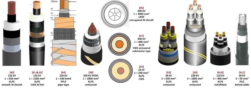
Figure 1 - The cables considered in the case studies
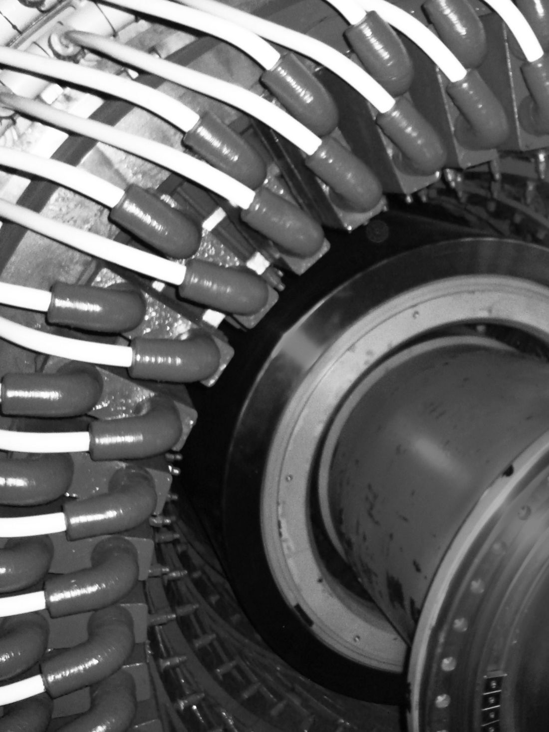
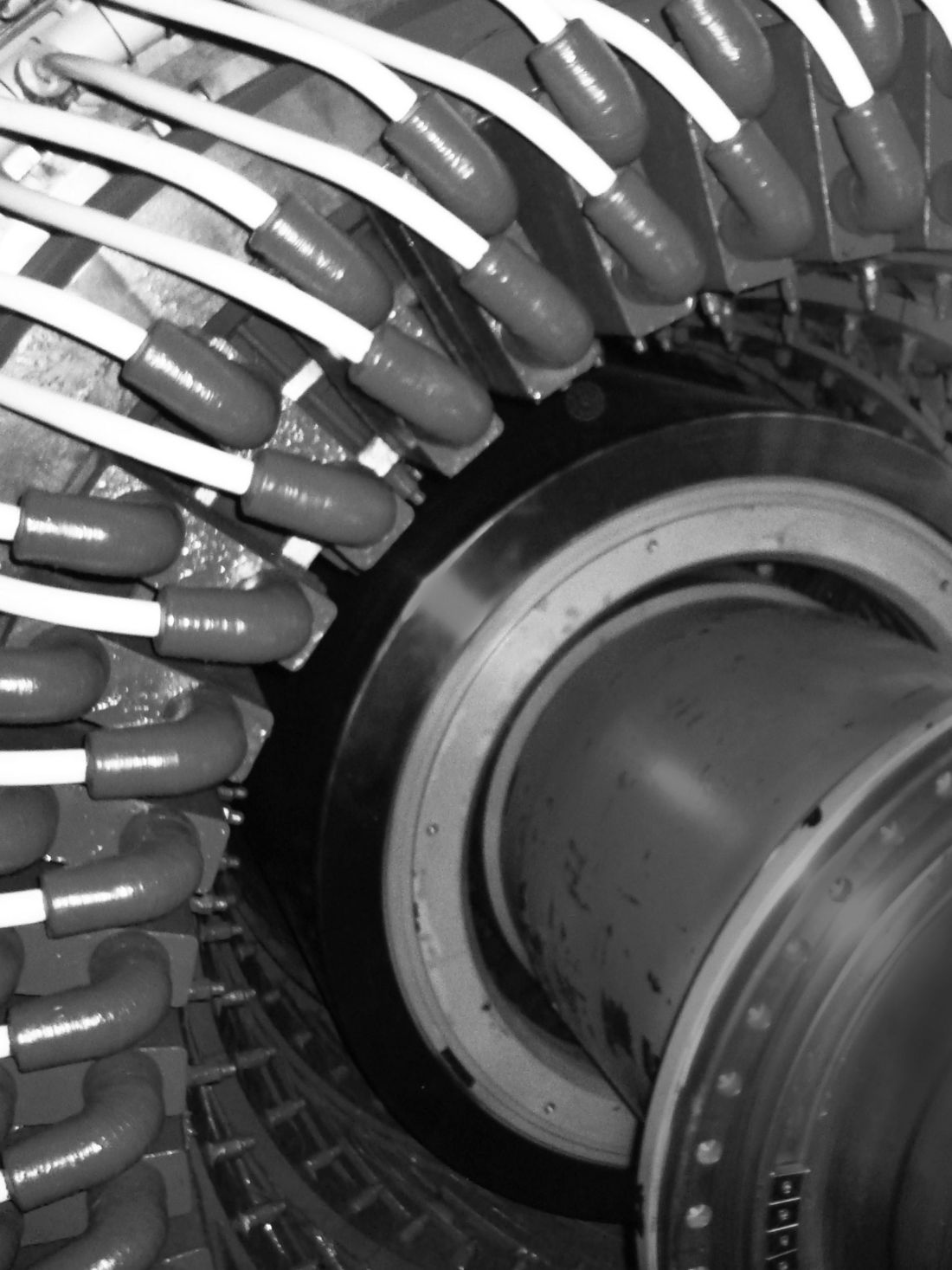
Also, there are varying laying conditions among the case studies, however the intent is that the cases remain sufficiently simple for illustration purposes. Configurations include single circuits in trefoil or flat formation, direct buried, in (special) backfill, in ducts, in troughs, in free air or in the sea floor. Figure 2 illustrates one of the considered laying conditions.

Figure 2 - One of the considered laying conditions
Bonding arrangements include both single, multiple and cross-bonding systems.
Together the case studies make up a set of examples with which a large part of the formulae in the IEC standards [2,3] can be verified.
Verification methodology
With the case studies, calculation techniques, tools or software can be verified. This can be an own crafted or commercially available software, numerical spreadsheet, custom-built calculation tool programmed in a scientific symbolic language or any other method, as long as it provides the current rating of a power cable in a user-defined situation.
The software, tool or technique may have a limited domain of applicability. It may for example be only meant for the calculation of AC power cables or for direct buried installations. Given the domain, the user will have to make a relevant selection of the case studies to verify the software with, and then to perform this set of calculations. The larger the set of case studies, the better the verification will be. Where possible it is recommended that the full set of verification case studies is used.
Subsequently, the intermediate and final results of the calculation software, tool or technique must be verified against the results listed in the CIGRE Technical Brochure. In the course of the work, the group learned that small deviations in one situation can have significant impact on the final results in other situations. Therefore, the group presents all (intermediate) results in at least 10 digits of accuracy, enabling the identification of small deviations. It is noted that all detailed results were agreed to by all experts in the Working Group.
Finally, the verification result must be reported. The workgroup recommends that the verification report, comprising the detailed alignment between the software, tool or technique and the case studies in the TB, is to be provided with the calculated current rating or with the software, tool or technique.
Interpretation of differences
A difference may be found between the calculation software, tool or technique and the results presented in the Technical Brochure. Noting that many experts agreed on the precise values mentioned in the TB, any difference should be investigated with the aim of understanding its origin and eventual correction of the calculation software, tool or technique. Any remaining differences should be explained in the verification report, such that all users know how well the software, tool or technique aligns with the case studies in this report, and what are the reasons for any remaining differences.
Key points of guidance
In this section, a subset of guidance points is discussed. The TB will comprise 49 guidance points, all of which are needed to consistently deduce the current rating in all case studies. These guidance points aim to remain close to the background of the IEC standards [2,3] while removing the sources for deviations from the optimal calculation procedure.
Accuracy
The first guidance point considers the accuracy of current rating calculations. When considering the accuracy of the calculations only, it is advised to round the final current rating as in Table 1.
Ratings (A) | 1 - 200 | 200 - 500 | ≥ 500 |
|---|---|---|---|
Round down to the nearest (A) | 1 | 5 | 10 |
Although a calculation can be made to great precision (e.g. 10 digits), the resulting current rating is not that accurate. Approximations are inherently made when applying the IEC standard approach since, for example, various calculation routines are based on experiments made many decades ago which have limits to their accuracy.
The largest inaccuracy is usually related to the values used for the soil thermal parameters that practically cannot be studied to the full extent. It is often worth spending more time and effort to understand these parameters better, rather than to spend time on improving calculation routines. Refer to TB 640, section 2.3 [1], for a thorough discussion of this topic.
Simplifications
The IEC rating standards [2,3] contain three key simplifications discussed below. These simplifications have been created in the past most importantly to allow hand calculation of the current ratings. Nowadays, the requirement to perform calculations by hand has disappeared and with it the reason for using such simplifications.
In addition, the power cable designs have changed, which leads to situations where the simplifications do not hold true anymore. This is shown in various of the case studies.
To avoid problems of validity with the existing simplifications in a calculation tool, technique or software, it is recommended to not simplify at all. This leads to:
- Not neglecting the eddy current losses. This means that these losses must be calculated in each situation when there is a continuous metallic sheath present.
- Always taking into account the dielectric losses. If they are negligible, this has no effect, but if they are not negligible after all, this approach ensures no wrong result is achieved.
- In the case of non-touching cables, do not use the simplified formulae for the calculation of T4 but use the general method for unequally loaded cables. In that, use the correct temperatures and losses of the cable conductors, screens, sheaths and armours.
Interpretation of information
Guidance is provided on how input information needs to be interpreted and how to handle the cases when this information is missing. A standard way of deducing information (e.g. cable dimensions) from non-perfect data sheets is provided such that different users can come to the same input data for a calculation. Also, information, descriptions and options are provided to come to an optimal set of input information for a situation in which the current rating has to be calculated. This includes a listing of additional material properties.
It was found that tapes or thin layers of material in power cables are often having significantly different properties in comparison with the insulation or jacket materials used in the cable description. In many calculation cases, different materials are combined. However, with this approach sometimes important differences from reality are introduced. Therefore, the guidance of the Working Group is not to combine layers of different materials in a cable, but instead to consider each layer separately in the calculations with its specific properties accounted for.
Lay lengths
In different situations, lay lengths play an important role in the calculation of the current rating. The consideration of these lay lengths is quite involved and leads to a number of guidance points.
Where an individual cable part is longer than the complete cable itself, lay lengths play a role and must be considered. This is the situation in:
- A laid up three-core or triplex cable,
- A manual calculation of the electric resistance of the conductor,
- A cable with a corrugated sheath.
These cases will be briefly discussed in the following subsections.
A laid up three core or triplex cable
When a three-core cable is manufactured, the cores are twisted together resulting in the cores inside of the cable being longer than the completed three-core assembly. This affects several parameters in the rating calculations. The lay length factor is computed as:
in which:
Length_of_lay is the axial cable length over which the cores make one full helical turn
Lay_diameter is the diameter of the mechanical neutral assembly. This is equal to 1.29 times the core diameter (derived in the TB)
Many parameters of the laid-up cores are affected by the lay length factor. The following adjustments should be made:
- If the IEC 60228 is applicable, no adjustment to the electrical resistance of the conductor has to be made, as the manufacturer must already have taken the lay length factor into account. This means that the electrical resistance must be representative for the finished three-core cable.
- If the IEC TR 62602 is applicable, the user should check if a lay length factor is used in the given electrical resistance. If not, the electrical resistance of the conductor must be multiplied with the lay length factor.
- If another approach is used to derive the electrical resistance of the conductor, the lay length factor typically has to be taken into account to deduce the electrical resistance to be used in the current rating calculations.
- The electrical capacitance of the core, the core / sheath resistance and the core / sheath reactance of the cable should be multiplied by the lay length factor.
- The thermal resistance T1 should be divided by the lay length factor.
- The thermal resistance T2 should partly (the laid-up part) be divided by the lay length factor.
Conductor electrical resistance calculation
When the electrical resistance of a stranded conductor is calculated manually, the length of lay of the individual strands has to be taken into account. Typically, stranded conductors comprise multiple layers of strands, which all have a different lay diameter and also typically have different lengths of lay. A direct calculation of the electrical resistance of a stranded conductor thus becomes involved and requires information that is normally not available for the user calculating the current rating.
An average lay length factor for all strands in a conductor can be defined. Then, when a conductor is built up from strands of uniform dimensions, the DC resistance of a conductor can be calculated given that average lay length factor. It was deduced that this average lay length factor is 1.05 for both copper and aluminium stranded conductors, but there is variation possible, typically leading to higher factors for conductors of 240 – 400 mm2.
Note that this lay length factor is different from the lay length factor of a laid up three core cable.
Cable with corrugated sheath
Similar to a length of lay, the additional amount of material resulting from the corrugation of a sheath must be taken into account. This is done by introducing a corrugation factor by which the electrical resistance of a smooth sheath is multiplied to yield the appropriate value for the corrugated sheath.
For both annular and spiralled corrugations of different types, the corrugation factor has been derived considering that the corrugations are made with circular (not sinusodial) shapes. This corrugation factor is:
With L and H defined as the width and depth and shown in Figure 3.

Figure 3 - Definitions in a corrugated sheath
Losses in screens, sheaths and armour
When calculating losses in power cables, discussions arise on how to calculate losses in the metallic screens, sheaths and armours. Many of these discussions originate from the fact that in today’s cable designs, several of these layers may be present, and may be separated electrically and thermally. This complexity leads to problems with the interpretation of the standards.
The Working Group has prepared charts showing which loss calculation must be performed for a specific cable design. An example of such a chart is given in Figure 4.
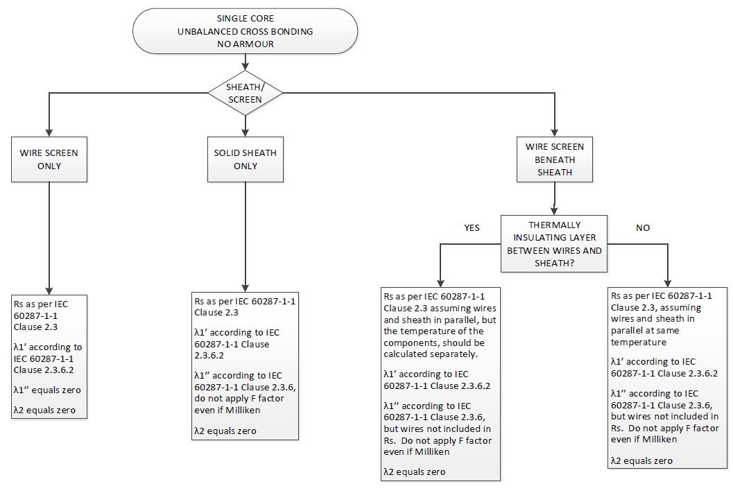
Figure 4 - One of the flow charts identifying the calculation method
It is noted that the calculations utilize the standardized loss formulae. A separate CIGRE Working Group (B1.64) is currently considering possible improvements in evaluation of the losses in three-core submarine cables. As these improvements will be dependent on the specific cable design, the possible improvements will be applicable to the selected designs only (potentially leading to a reduction of calculated losses, and hence an increase of current rating).
Regarding armour losses specifically, the Working Group considered how to avoid some of the limitations in the current standards.
Various case studies were performed in which the armour plays an important role. For example, a case study is comprised for a cable with a flat wire armour in a steel pipe. This situation represents a land situation in which an existing steel pipe is used to house a three-core XLPE insulated cable system.
The IEC limits the calculation of the AC resistance of magnetic armour wires to wire sizes between 2 and 5 mm. The WG guidance is to use a linear dependency of the AC resistance from 1.2 to 1.4 times the DC resistance when the wire diameter changes from 2 to 5 mm, and to also use this relation also for wire sizes outside of this range, while noting that thicker wires are common, but wires smaller than 2 mm are not common.
Further guidance was provided for flat wire armour, where the loss factor is proposed to be calculated based on the smallest dimension of the flat wire.
T2 of three core cables
In the case of three core cables, the thermal resistance between the sheath and armour must be calculated. This calculation is not well defined in the standard and, therefore, the TB redefines the calculation process for T2. The procedure is to add the thermal resistance of the individual core jackets (with an additional division by three as there are three cores) to the thermal resistance of the fillers between the phase cables / cores and the bedding. In the latter calculation, (only) one geometric factor is used (the IEC standard has two such factors). It is noted that in this calculation, the thermal resistance of the filler and the bedding must reflect the thermal resistance materials in dry conditions, using a worst-case approach.
The WG notes that if the filler has voids which are water-filled, the thermal properties of only the filler are to be considered. If the filler has voids which are air-filled, also in rope filler constructions, the thermal resistivity may be high. Careful consideration should be given to the value of the representative thermal resistivity in these cases.
HVDC cables
In the case of HVDC cables, there are two limitating criteria when computing the ratings. One is the maximum conductor temperature and the other is the maximum allowable electric field strength in the insulation. The latter leads to a limit on the temperature drop across the insulation that ultimately limits the maximum conductor temperature and current carrying capacity.
In a HVDC cable, the electrical field is determined by the resistive properties (governed by the specific electric resistivity ρ) of the insulation material, contrary to a HVAC cable where this is determined by capacitive properties (governed by the dielectric permittivity ε). Since the temperature distribution depends on the loading conditions, the electrical field distribution across the insulation thickness will accordingly vary with the current carried by the cable. In order to ensure that the electrical fields in the insulation material remain within limits, the temperature difference across the insulation material is limited. This limit may be more stringent than the limit on the maximum conductor operating temperature with typical values between 10 and 15 K.
It is noted that the maximum temperature difference across the insulation is an important parameter during type testing and should not be surpassed during cable operation.
To take this additional limitation into account, the guidance given is that HVDC cable current ratings can be calculated by applying the IEC standards, but the limit on the temperature difference over the insulation material excluding semiconducting screens has to be taken into account as well. The precise limiting value is verified through the type test of the specific HVDC cable under consideration. Both the limit on the maximum operating temperature and the temperature difference over the insulation must be obeyed at all times.
Future work
The verification of the current rating calculations will be continued by CIGRE WG B1.72. A number of more complex case studies for which further calculation and interpretation difficulties must be overcome, will be considered. These case studies will include:
- Dynamic, emergency and cyclic rating of a single cable circuit
- Cables in a horizontal directional drilling with three cables in one pipe and three cables in separate pipes enclosed in another pipe including a spare
- Multiple circuits in parallel with thermal and electrical effects
- Cables close to an external heat source
This selection is based on multiple sources including the questionnaire as reported in TB 640 [1]. These additional case studies and further resulting guidance points will be reported in a further CIGRE Technical Brochure which is expected late 2022.
References
- CIGRE Technical Brochure 640, A guide for rating calculations of insulated cables, CIGRÉ (2015-12): https://e-cigre.org/publication/640-a-guide-for-rating-calculations-of-insulated-cables
- IEC 60287-1-1, Electric cables – Calculation of the current rating – part 1-1: current rating equations (100% load factor) and calculation of losses – General, IEC, (2014-11)
- IEC 60287-2-1, Electric cables – Calculation of the current rating – part 2-1: Thermal resistance – Calculation of thermal resistance, Edition 2.0, IEC, (2015-2).

Other Technical Brochures