Correct handling of fittings and conductors for overhead lines
Given that many problems experienced in the field are perceived to be due to poor handling and installation practices, the Working Group carried out a survey of current practice by manufacturers, contractors and utilities with regard to correct handling and installation of fittings and conductors.
This was done by means of a questionnaire and subsequent analysis of the responses together with inputs from the experts in WG B2.50 and TAG B2.06. Replies were received from Australia, Austria, Brazil, Canada, France, Germany, Italy, Japan, New Zealand, Norway, South Africa, Spain, and, UK.
Guidelines have been produced with the aim of promoting good practice to minimise handling and installation problems with fittings & conductors.
Members
Convenor (AU)
P. DULHUNTY
Secretary (RU)
S. KOLOSOV
W. TROPPAUER (AT), J.M. ASSELIN (CA), P. CHAN (CA), D. HAVARD (CA), J.P. PARADIS (CA), P. VAN DYKE (CA), B. LIU (CN), A. GRAVELMANN (DE), C. ROZÉ (FR), V. CHARI (IN), U. COSMAI (IT), K. HALSAN (NO), B. JACOPS (SA), B. WAREING (UK), J. HAVEL (US), N. SAHLANI (US), D. SUNKLE (US), C. TAMM (US)
Corresponding members
D. BRAGA (BR), S. THADDEY (CH), D. GOMEZ (ES), M. MITO (JP), J. ALMANO (NZ), B. HARIDASS (SA)
Reviewers
H. LUGSCHITZ (AT), F. GOFFINET (FR)
Introduction
This guide is not intended to cover conductor creep or wrongly manufactured or wrongly designed fittings.
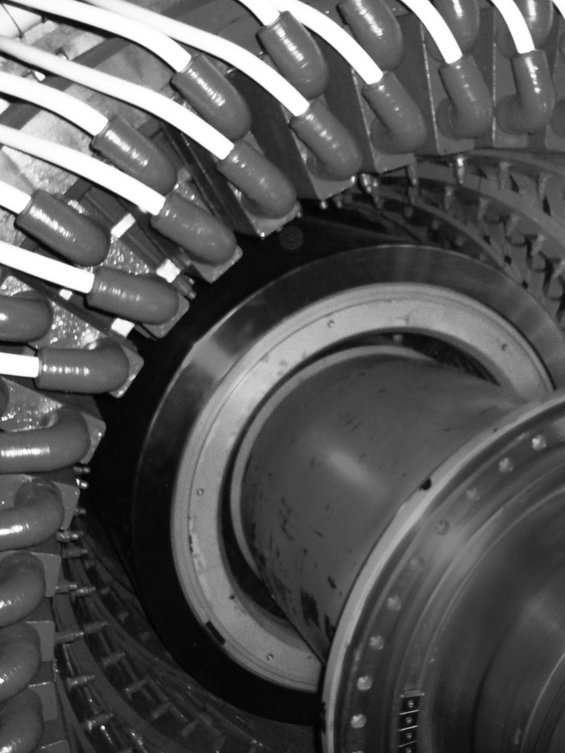
Fittings are primarily designed from a mechanical point of view (Figure 1) respectively to withstand short circuit currents up to one second. In service, these fittings are mainly exposed to static and dynamic mechanical loads as well as short circuit currents and environmental influences. Thus, the mating surfaces, the string design and minimisation of torsional, bending, and uneven stresses in the fittings comes from good installation practice.
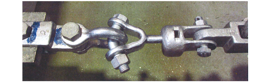
Figure 1 - Fittings being tested for elongation and tensile strength are clevis-tongue, bow shackle, ball Y-clevis, socket clevis, clevis tongue
Due to the very wide range of line items captured under the general description of "fittings", an illustrated glossary of terms is included as an appendix.
Given that many problems experienced in the field are perceived to be due to poor handling and installation practices, the Working Group carried out a survey of current practice by manufacturers, contractors, and utilities regarding correct handling and installation of fittings and conductors.
This was done by means of a questionnaire and subsequent analysis of the responses together with inputs from the experts in WG B2.50 and TAG B2.06. Replies were received from Australia, Austria, Brazil, Canada, France, Germany, Italy, Japan, New Zealand, Norway, South Africa, Spain, and UK.
Questionnaire summary
The types of issues were analysed from the replies obtained and they are grouped as shown in Figure 2. It can be determined that there are four main construction issues:
- Compression
- Installation
- Vibration dampers and spacers
- Insulator issues
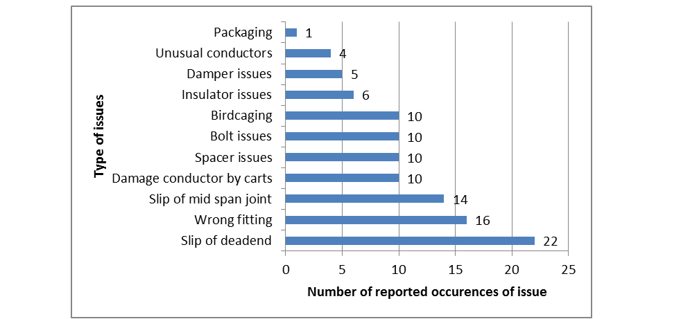
Figure 2 - Line issues
Improper conductor preparation – brushing, cleaning, why
The number one cause of connector failures is, by a majority of nearly 75% of all recorded failures, associated with improper conductor preparation! Most linemen are taught to brush the conductor, but inappropriately told that the purpose is to remove the oxides. Aluminium oxide forms on the surface of aluminium in milliseconds, and before you can get the brush to the end of the stroke, it has grown back on the surface. A major mistake is made in assuming that new conductor, which appears “bright and shiny” is clean of oxides, and makes a better connection – and therefore, because they have been inappropriately instructed, linemen assume it is better not to brush it – because after brushing, it looks dull and ugly. The primary purpose of brushing the conductor is to provide a ROUGHENED SURFACE which will ultimately make a better electrical contact than the shiny surface.
It is imperative, even with new conductor to brush the surface aggressively. The brushing should be accomplished using a clean stainless steel wire brush or a brass wire brush or an abrasive fleece. Ferrous steel brushes leave “rust residue” which will contribute to problems with the connection over time and should not be used.
Safe Handling of conductors
There are many opportunities for conductors to get damaged during construction of transmission lines. Almost every operation, from receiving and handling reels to sagging in, is susceptible to damage unless some precautions are taken. The main types of damage that can occur to a conductor may be broken down into three broad categories:
- Surface defect (Figure 3), where the conductor surface has been nicked or scratched, dented or smashed. The depth and extent of damage determines the repair method to be used. Simple abrasion, nicks, protuberances, can be sanded down using emery cloth or fine sand paper. The use of steel wool is not recommended since it could leave hair-like residue that could lead to corona problems later on. In cases where individual wires have been severely gouged or broken, it may lead to an unacceptable loss of strength, and the conductor section must be cut out or repaired with preformed rods or compression repair sleeves. A discoloration of the conductor's surface is sometimes observed after ocean shipment due to contact with salt water. This discoloration does not affect the performance of the conductor.
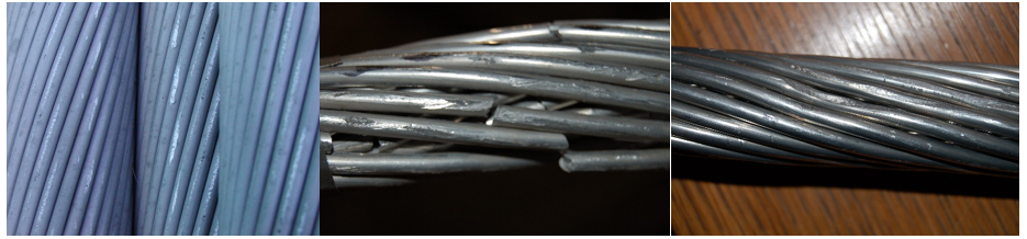
Figure 3 - Surface defects: Left: Abraded surface, Middle: Broken wires, Right: Drake AACSS with indentations from Klein gripa
- Popped wire (Figure 4), sometimes called proud wire, is the phenomena by which a wire is forced out of the outside layer of the conductor. It occurs when the conductor is subjected to torsion and the wire is more or less wrung out of place. This happens most frequently around sheaves and travellers. Note that it can also be the result of poor manufacturing. Popped wires produce corona and radio noise problems and in general should be dealt with by either carefully hammering them back into the conductor with a wooden mallet, or cutting them out, covering the cut ends with preformed rods. Type 4 conductors having up to 30% of damaged aluminium wires may be repaired using high temperature armour rods with grit glued to the inside of the rods.
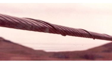
Figure 4 - Popped wire
- Birdcage (Figure 5) is usually the result of over stretching the outside layer of the conductor. In some instances, it can be caused by an accumulation of slack in the conductor. A birdcage can lead to both electrical and mechanical problems. Generally, birdcages cannot be fixed. For homogeneous conductors (ASC, AAC, AASC, AAAC, ACAR), where the birdcage diameter is within 2 to 3 times the conductor diameter, they may be ignored, as it is likely that the birdcaged wires will eventually take up their share of the tensile load as creep takes place in the conductor and disappear. In other cases, they will have to be spliced out.
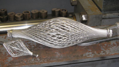
Figure 5 - Birdcage
Other types of defects occur but are usually a combination of the three listed above. In most cases, the affected part of the conductor must be spliced out.
General conclusions
The responses to the survey highlighted that most problems are with compression fittings. It may be wise to train linemen by compressing spare conductors at ground level before taking the hydraulic compression tools in the air.
ELECTRA, is the digital magazine of CIGRE, you can obtain access as part of a CIGRE membership. Find out more about joining options here.
Other Technical Brochures