Survey on industry practices and effects associated with the cutting out of stator coils in hydrogenerators
Operation of hydrogenerators with cut out faulted coils is a common practice in the industry, this is often done within acceptable limits of voltage unbalance. The purpose of this brochure was to explore and document industry experience on cutting out of faulted stators coils including the cause of the faults, techniques to locate the fault in the windings, considerations for repair methodology chosen and effects or encountered problems of cut out coils.
Members
Convenor
(CA)
C. MILLET
Secretary
(UG)
J. AKIROR
J. PEDNEAULT-DESROCHES (CA), P. WIEHE (AU), S. COTNER (US), O. KOKOKO (CA), A. MERKHOUF (CA), J. ROCHA (BR)
The stator winding is one of the key components in a hydrogenerator. When a stator ground fault occurs in the hydrogenerator during service, it is not always possible to immediately proceed with replacement of the faulted coils. However, often due to commercial or contractual reasons the generator must be returned back to service as soon as possible. The quick solution is often to cut out the faulted coils and to operate the generator with an acceptable voltage unbalance until a scheduled outage period in which the faulted coils can be replaced.
While the replacement of form-wound bars can be quite easy to perform with skilled personnel as long as spare bars are available. The situation is quite different when the replacement of multi-turn coils is required. In this case, one solution which requires highly skilled personnel and a significant amount of work is:
- to cut the airgap leg of some good coils,
- remove and replace the faulted coils,
- splice the new airgap coil legs into position.
The other solution, which is much easier to perform and will cost much less, is to cut out and bypass the faulted coils and to operate the generator with a voltage unbalance until it is rewound.
The Technical Brochure describes the different practices associated with cutting out coils and gives guidelines on the best practices to ensure safe operation of the generator with cut out coils.
Contents of the Technical Brochure
The Technical Brochure consists of 5 chapters and appendices as follows:
Chapter 1: This chapter provides a background and purpose of the TB supported by industry knowledge from several references and survey responses.
Chapter 2: This chapter provides information on stator windings, the types of stator windings, an educational section on the basics of winding diagrams - reading and drawing winding diagrams, calculation of winding factors, types of winding connections etc. These are aimed at providing the necessary technical information required to read and understand a winding diagram and identify where in the diagram the faulted coils are located.
Chapter 3: This chapters provides a technical guide on:
- How to find a fault on the stator winding for solidly grounded and unsolidly grounded coils
- Disconnection of a faulted coil and condition assessment of the rest of the coil
- Damage analysis of the fault on the winding and the core
- Winding repair method on:
- How to disconnect a coil
- Bypass and open a coil
- Splicing a top coil leg
- Replacing a complete coil
- Disconnecting a circuit among others
- Electrical tests required on the rest of the coil after disconnection of the faulted coils
- Measurements before returning the generator to service
- Methods to reduce the unbalance between circuits
- Spare parts required for coil replacement for lap or wave, top and bottom bars
This chapter also provides guidance on means to mitigate the negative impacts on the generator output by selecting good coils of the same voltage contribution in the circuit voltage build-up. In certain circumstances, one coil can be cut out without major consequences for the rating of the generator. In other circumstances, which is for the majority of the cases, good coils must be bypassed to balance the winding to avoid a significant derating of the generator.
Chapter 4: Presents the results from the industry survey of owners of small and large hydro facilities with representation from Canada, Germany, Portugal and USA. The survey was also responded to by manufacturers, consultants and researchers from Brazil, Canada, Croatia, Germany, Italy and USA.
The survey explored circumstances in which a fault occurs, techniques used to locate the fault, repair options adopted, techniques used to open a coil, disconnection of circuits, problems encountered with cut out coils, predictive calculations to determine other effects of cut out coils, procedures to return the generator to service, balancing of the winding etc.
Chapter 5: Provides an analysis of the collected data from the survey with respect to the repair works done, calculations and measurements undertaken in balancing the winding. The survey participants highlighted the need for a technical guide on how to cut out coils.
Appendices include:
- Definitions, abbreviations and symbols used
- Links and references
- Questionnaire circulated
Educational section on the stator winding diagram
The aim of this section is to provide sufficient knowledge to generator users to understand, draw up from scratch and use a winding diagram to determine in which phase and in which circuit the failed coil is located. This section also provides a means to calculate the voltage contribution of every coil in a stator winding and information that would be useful in calculation of the voltage unbalance in the coils after cutting out of coils.
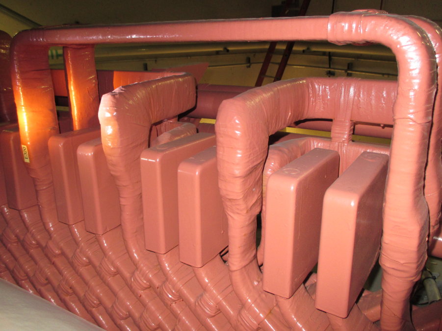
Stator windings of hydrogenerators are mainly made with two-layer form-wound multiturn coils, lap Roebel bars or wave Roebel bars. The characteristics of these types of winding and their type of connections are fully described using pictures and diagrams. What to expect in a winding diagram is also highlighted.
Occasionally, a winding diagram is not available hence the need for skills to draw up a winding diagram from scratch using key observations and any other available information in the existing drawings. Known parameters like the slots per pole per phase can be used to draw up the coil group distribution for the winding, examples of these are given in the TB for better understanding. Other calculated factors like the skew factor, pitch factor, distribution factor, winding factor are used to calculate the induced voltage in a coil leg from which the total induced voltage per phase can be obtained.
Multiturn coils
One layer of jumpers
Lap bars
Two layers of jumpers
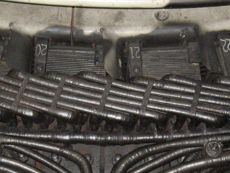
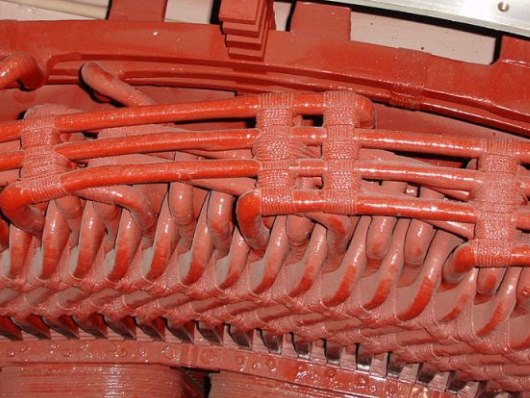
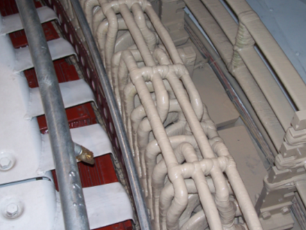
Figure 1 - Short jumpers 1 to 4 connecting adjacent coil groups of the same phase of opposite polarity (above), Long jumpers 1 to 7 connecting adjacent coil groups of the same phase of the same polarity (Bottom)
Technical guide
Hydro generators have protection systems that detect faults in the stator, often the actual location of the fault on the winding needs to be physically determined and fully accessed. Tests like the insulation resistance of each winding, DC high pot test and visual inspection can narrow the search to a specific phase and circuit. Further tests are required depending on whether the faulted coil is solidly grounded or not to identify the actual faulted coil, which can then be disconnected by the appropriate method.
This section in the TB describes in detail how to find a fault, how the repair could be done and which actual tests are recommended before returning the generator to service. When a stator fault occurs and the damage has been evaluated, prior to starting work on bypassing coils, it is recommended that a skilled person makes an evaluation of the winding unbalance that will be produced by the bypassed coils and calculate what would be the derating of the generator to avoid the overheating of certain parts of the windings. This evaluation would help determine and recommend the most economical repair procedure among:
- Just bypass the damaged coils
- Bypass of damaged coils and bypass of good coils to balance phase circuits
- Disconnection of phase circuits; and
- Rewind of the stator.
Details of each procedure are provided including bypassing a failed coil, splicing top coil legs to replace a complete coil and disconnecting a complete circuit. A proposed list of required spare parts is provided for the replacement of any individual coil or bar located either at the top or bottom slot for the different types of winding.
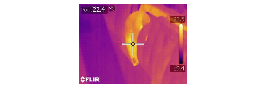
Figure 2 - Faulted coil detection using a variable power supply and an infrared camera
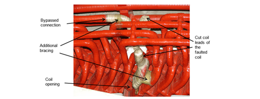
Figure 3 - Cut and bypassed coil
As a general rule, bypassing a single coil may result in derating the unit when coil group connections are long (1 to 7) without balancing of the winding by cutting out good coils.. On the other hand, a single coil may not result in derating the unit when coil group connections are short (1 to 4) and if there are more than 15 coils in the parallel circuits. Nevertheless, it is recommended to monitor the current in the winding circuits before returning the generator to service to ensure that the current in the parallel circuits is in an acceptable range. Circulating currents between parallel circuits increase the temperature rise of some of the parallel circuits that may consequently result in the derating of the generator. Also the voltage unbalance between circuits following the cut out and bypassing of coils should be kept at acceptable limits. As a result some electrical tests and measurements are required to ascertain the new operating conditions of the generator before its return to service.
Main results
Questionnaires were distributed to generator users and manufacturers in various countries to gather information concerning practices and effects associated with the cutting out of stator coils in hydrogenerators. The sample space involved;
- hydrogenerator owners or operators with a total average installed capacity of 15 GW and an average of 194 units with the largest unit of 440 MVA,
- manufacturers with contract agreements for investigation, repair works and testing,
- consultants and researchers from a research institute.
| Country | Total capacity (MW) | Number of units | Number of powerplants |
|---|---|---|---|
Canada | 5 200 | 97 | 15 |
Canada | 39 406 | 342 | 61 |
Germany | 3 000 | 39 | 13 |
Portugal | 6 600 | 148 | 69 |
USA | 20 900 | 345 | 75 |
Average | 15 021 | 194 | 47 |
Cause of winding fault
Results from the survey clearly indicated that the majority of faults in hydrogenerators mainly occurred during operation due to the aging of the stator winding. Other predominant failures are those due to the projection of foreign material coming from the rotor and those occurring during routine electrical tests.
| Type of fault | Occurrence |
|---|---|
During operation due to aging, turn-to-turn failure, excessive core and end-arm vibration | 92% |
Projection of foreign material coming from rotor | 77% |
Routine electrical test like hi-pot, DC ramp, etc. | 69% |
Projection of material coming from the stator (e.g. broken clamping finger) | 62% |
Foreign object left in the stator | 46% |
Damage caused during inspection, works or repair | 46% |
Accidental activation of the deluge system | 15% |
Infant mortality | 8% |
Method to determine location of fault
A visual inspection is primarily performed to locate signs of the fault. Then, depending on the fault location, e.g.: inside or outside of the stator core, and on its resistance to ground, a variety of voltage sources, current sources and surge generator could be used to locate the exact location of the fault with sparks, noise or smoke.
| Resistance to ground of the fault | Dead ground | Low resistance | High resistance |
|---|---|---|---|
Visual inspection | 93% | 77% | 70% |
DC Hi-pot | 79% | 69% | 70% |
AC Hi-pot | 43% | 46% | 30% |
Current source for smoke | 64% | Not used | Not used |
Current source and measurements of Amp or Temp | 3 | 31% | Not used |
Voltage source and Variac (120Vac or 600Vac) | 50% | 54% | 40% |
Surge generator on coils | 21% | 23% | 30% |
Run generator - smoke | 7% | Not used | Not used |
Surge generator on bars | Not used | Not used | 20% |
Other: Capacitive discharge | 14% | Not used | 10% |
Other: Surge generator on end-arm | Not used | 8% | Not used |
AC / DC tests | Not used | 8% | Not used |
Repair options
From the results, failed Roebel bars are immediately replaced by spares if available however common practice also shows that they are often bypassed temporarily before a scheduled outage or before spares are available.
| Type of repair | Occurrence |
|---|---|
Always immediately replaced by spares | 73% |
Bypassed temporarily before scheduled outage and availability of spares | 55% |
Permanent bypass | 27% |
Another unexpected result is that just a little more than 50% of failed multiturn coils are left in place, cut out and bypassed permanently.
| Type of repair | Occurrence |
|---|---|
Permanent bypass | 52% |
Temporary bypass | 48% |
The commonest repair technique is cutting and removing top coil legs, and replacing the damaged coil. Other techniques used to replace multiturn coils are those listed in the table below.
| Type of repair | Occurrence |
|---|---|
Cut and remove top coil legs, replace the damaged coil and splice new top coil legs | 60% |
Cut and remove a damaged top coil legs and splice new one | 50% |
Open a span performing a lift and replace the failed coils having thermo-setting insulation | 40% |
Open a span performing a lift and replace the failed coils having thermo-plastic insulation | 40% |
Replace basket type, hair-pin or horse-shoe coils like bars | 20% |
Encountered problems with cut out coils
The most encountered problems when returning a generator to service are excessive temperature rise of the stator, stator vibration and Mvar absorption restriction (i.e.: leading power factor with field under excited). These problems are mainly observed on multiturn coil windings. They are due to misevaluations of the generator derating, the stator winding temperature rise and the current in each parallel circuit.
| Problem | Occurrence |
|---|---|
Excessive temperature rise of the stator winding | 5 |
Stator core vibration | 4 |
Mvar absorption restriction (leading power factor) | 4 |
Damper bars overheating | 2 |
Stator core hot spots | 0 |
Others | 5 |
Predictive calculations before winding repair
The predictive calculations made before the winding repair are those relative to the generator derating, the stator winding temperature rise and the value of the current in each parallel circuit. These calculations are mainly performed with an in-house developed calculation method which excludes any finite elements method (FEM).
| Calculation | Occurrence |
|---|---|
Generator derating | 71% |
Stator winding temperature rise | 50% |
Currents in each parallel circuit of each phase | 50% |
Phase angle of the cut out coils relative to the phase voltage and voltage build-up of circuits and/or phases | 29% |
Currents in the split-phase transformer of each phase | 21% |
Current in the damper winding | 7% |
Negative sequence currents | 0% |
Damper bar temperature | 0% |
Stator core vibration | 0% |
| Calculation method | Occurrence |
|---|---|
In house developed calculation method (excluding finite elements method) | 70% |
Electromagnetic finite elements model of the generator | 40% |
Externally developed calculation method | 40% |
Balancing the winding
Where required, different methods can be used to balance a winding. As necessary, the bypass of good coils is made for either one of the two following considerations. The first one is to balance the currents at the split phase differential protection with the bypass of equivalent good coils in the other split phase of the same phase. The second one is to avoid negative sequence currents in the three phases of the generator with the bypass of equivalent good coils in the two other phases. Nevertheless, the replies to the questionnaire where those listed in the Table below.
| Attempts to balance a winding are done? | Ratio |
|---|---|
In order to balance the currents of all circuits of all phases | 62% |
In order to balance as much as possible the split phase currents | 38% |
Never | 23% |
In order to mechanically balance the stator | 15% |
Only if it is necessary to reduce the unbalance | 15% |
No precise requirements were provided by the survey responses on the number of coils to cut out in a winding circuit or in a phase except that it seems the number of coils that can possibly be cut out in a circuit should be less than 10% of the total coils in a circuit. Nonetheless, the TB details criteria used to select appropriate balancing coils.
Conclusion
The survey has outlined that in most cases, the stator windings need to be balanced with the disconnection of good coils when failed coils are cut out and bypassed. This situation seems to be particularly true where the coil group connections in the winding are long (1 to 7) connecting a coil group to the adjacent one of the same phase having the same polarity. However, balancing seems to be less required where the coil group connections in the winding are short (1 to 4) connecting a coil group to the adjacent one of the same phase having a polarity inversion. Nevertheless, no definite rule can be made on whether or not to balance a winding since hydrogenerators are all different in design and the number of cut out coils and their location in the winding presents differently each time.
The survey also pointed out the fact that there is a lack of commercially available tools for the calculation of circulating currents, stator winding temperature rise of each parallel circuit and generator derating with consideration to the number of cut out coils, their position in the winding and the winding configuration (i.e., sequence of the coil groups, type connections between coil groups, etc.). It seems that a calculation tool based on the abc frame methodology would be interesting to develop.

Other Technical Brochures