Evaluation of Temporary Overvoltages in Power Systems due to Low Order Harmonic Resonances
Temporary Overvoltage (TOV) is a typical phenomenon accounted for in insulation coordination studies. This overvoltage is defined by IEC as a “power frequency overvoltage of relatively long duration” and the standard testing waveform follows this definition by consisting of a “short-duration power frequency test”.
Members
Convenor (DK)
F. FARIA DA SILVA
Secretary (NL)
K. VELITSIKAKIS
TF Leader (SE)
O. LENNERHAG
F. BARAKOU (NL), A. CRUZ (BR), J. MICHEL (FR), D. MILLS (UK), K. MUNJI (UK), J. PENG (UK), I. RAHIMI (CA), C. SKOVGAARD (DK), I. TANNEMAAT (NL)
Reviewers
M. MARTINEZ DURO, S. RAMADHIN, M. VAL ESCUDERO
It is expected that the duration of a TOV affects the withstand characteristic and this was recognised by CIGRE in 1998 with the publication of the withstand voltage curves (Figure 1) as a function of time for different equipment (in, “Temporary Overvoltage Withstand Characteristics of Extra High Voltage Equipment”, ELECTRA 179).
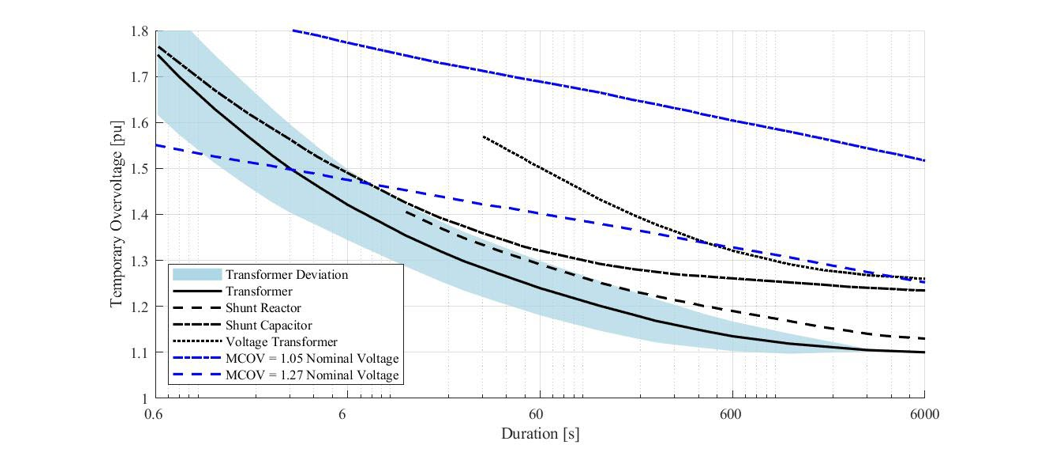
Figure 1 - TOV withstand characteristics of HV equipment at power frequency
An important facet lacking in the IEC standard and other reference documents is that frequencies other than power frequency are not accounted for. As IEC notes when defining TOV, “In some cases its frequency may be several times smaller or greater than power frequency.” Likewise, the CIGRE reference document from 1998 states that “This problem should be a subject of further investigation”.
The Technical Brochure (TB) proposes to shed some light on the subject by focusing on TOVs due to low order harmonic resonances. This type of TOV was not prevalent until recently, but it is becoming more probable due to the increasing usage of cables in transmission grids, the longer distances between the meshed grid and large energy centres connected using radial links (e.g., offshore wind parks), and a reduction of network strength (i.e., lower short-circuit power). All these factors contribute to the shift of resonances to low harmonic frequencies (e.g., 2nd or 3rd). If excited by a harmonic current (e.g., transformer(s) saturation during a scheduled energisation or during fault clearing), a TOV occurs containing both the power frequency component and a noticeable harmonic component. The withstand voltage in this condition is neither defined in the literature nor part of the standard equipment testing, raising questions regarding the potential impact of these TOVs on the equipment’s aging, deterioration or even failure.
This TB introduces a general description of events that may result in a TOV, focussing on aspects related to low order harmonic resonances. The impact of this harmonic component on the insulation of transformers, shunt reactors and surge arresters (SAs) are described. A new method for modelling and selecting surge arresters is introduced for the simulation and study of TOVs with harmonic content.
Moreover, various methods for the assessment of the TOV containing low order harmonics are presented and described in detail. The methods are used by system operators and power system experts, and their developments originate from different assumptions. As a result, it is possible that the methods result in different outcomes; therefore, their theoretical background should be understood by the user. More specifically, the assessment methods for these TOVs are:
- Moving windows method using RMS and peak values: A moving window is shifted through the waveform by a fixed time step, and the maximum RMS and peak values are saved. The process is repeated for different moving window sizes, which are defined as an integer multiple of the power frequency period. The saved values are then plotted in time-voltage plane, with the window size corresponding to time/duration, and are compared against the reference withstand curves. The RMS values represent the thermal stress and the peak values the dielectric stress.
- Consumption of a gauge method: Developed jointly by a system operator and two transformer manufacturers, the method associates different overvoltage limits, from the higher to the lower, to an “acceptable” overvoltage duration. The term “gauge” corresponds to reference tables with the phase to phase and phase to ground voltage limits for different transformer types.
- Frequency-based assessment for power transformers method: It considers that the breakdown strength of transformer insulation is influenced by heat storage and dissipation. The power frequency withstand voltage of transformers - which should be an available information- is converter by the ratio of dielectric strength for the dominant harmonic frequency of the TOV.
- Surge arrester evaluation method: The surge arresters’ energy absorption is obtained through EMT-type simulations and the results are checked against the surge arresters’ energy capability. For the evaluation of TOVs with harmonic content, a minimum V-I characteristic is defined and should be used to model the surge arrester(s), as proposed in the TB .
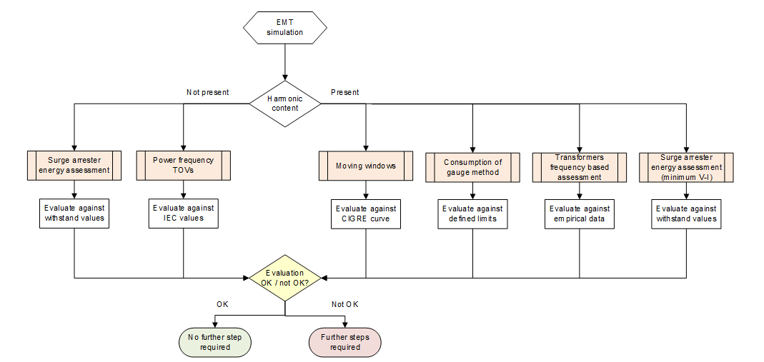
Figure 2 - Flowchart for TOV assessment
Additionally, the TB provides guidelines on how to approach and to perform harmonic resonance TOV simulation studies. For that reason, a test grid is used to generate such TOVs from different events (e.g., power transformer energisation, fault clearing, auto-reclosure, …). Thereafter, the described assessment methods are applied for some of these TOVs, aiming to both demonstrating their implementation and setting a comparison reference for the reader. As an example, Table I shows the comparison of the different methods for a fault clearing event next to two transformers for different loading levels. In this particular example, it is shown that all methods indicate no risk if the loading is higher than 50 MW, however, two of the methods indicate the need for a more detailed analysis for a system loading lower than 30 MW.
ELECTRA, is the digital magazine of CIGRE, you can obtain access as part of a CIGRE membership. Find out more about joining options here.
Other Technical Brochures