Surge and extended overvoltage evaluation of HVDC cable systems for testing
Stress profiles in HVDC cable systems can differ considerably from the ones seen in AC systems. Ensuring that the tests performed on the system are sufficient to ensure its reliability is a significant concern. This brochure presents a detailed analysis of the parameters that can affect the characteristics of fault waveshapes, as well as it considers the necessity and feasibility of a specific test.
Members
Convenor (SE)
Markus Saltzer
Secretary (FR)
Vincent Joubert
Carsten Bartzsch (DE), Simon Wenig, YM (DE), Jon Ivar Juvik (NO), Alessandro Crippa, (IT), Hani Saad (FR), Bahram Khodabakhchian (CA), Roland Zhang (DE), Max Görtz, (DE), Luigi Colla (IT), Tanumay Karmokar, (DE), Willem Leterme, (BE), Giovanni Mazzanti (IT)
Corresponding members
Jan Lundquist (SE), Uwe Riechert (CH), Hideki Motoyama (JP)
Introduction, Scope and Objectives of this Technical Brochure
Recent developments in High Voltage Direct Current (HVDC) converter technology, and in particular Voltage-Source Converter designs (such as the Modular Multilevel Converter), have allowed for a considerable increase in power transmission links, in particular with underground or subsea cables. At the time of the inception of the Working Group, the qualification of these cable systems was primarily done following international recommendations, such as CIGRE TB 496. However, several gaps were identified, that were not covered in existing recommendations:
- Testing waveshapes during the qualification of HVDC cables have largely been inherited from recommendations for HVAC systems. It remained an open point whether these qualification waveshapes (such as superimposed impulses) were sufficient to cover voltages applied to the system in case of faults in HVDC systems (both during AC-side and DC-side faults).
- Similarly, while lightning impulse tests were present in existing recommendations, no guidance existed on how to determine project-specific values that would apply to HVDC systems, particularly in the case of mixed overhead-underground links.
- No recommendation exists on how to consider specific configuration, or emerging technologies (parallel AC-DC systems, DC-breakers, multi-terminal systems)
The joint working group JWG B4/B1/C4.73 was tasked with investigating these aspects, and providing inputs for future recommendations (leading, in particular, to the introduction of the TOV test in recommendation TB 852, which followed TB 496).
Structure and Content of the Technical Brochure
The brochure starts with an overview of current practices regarding HVDC cable systems and their qualification. Chapter 1 gives a rapid overview on converter and cable technologies and of the possible system configurations, before presenting a list of past and ongoing projects and the voltage levels used in their qualification.
Chapter 2 presents the extensive Electro-Magnetic Transient simulation work performed by the joint working group in order to characterize events appearing in MMC-HVDC systems with extruded cables.
The simulations are mostly performed considering a symmetric monopolar system (half-bridge), with a determination of the relevant project parameters. Based on these simulations, a synthetized waveshape is proposed for the healthy pole voltage in case of pole/cable fault (DC-LTOV), intended as a representative curve depending on system parameters.
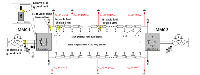
Figure 1 - Schematic overview of investigated symmetrical monopolar MMC-HVDC link
The rigid bipolar configuration is also covered (albeit with less extensive simulations), and the validity of the overall conclusion for the monopole is considered.
An overview of the effect of lightning in mixed overhead lines-underground systems is given, with an example of a parametric study performed to determine the relevant levels.
Based on the synthetized waveshape previously determined, Chapter 3 examines the effect of this overvoltage in the cable system insulation, in particular to determine, looking at the insulation electric fields caused by such events, whether these effects are covered by previously existing qualification tests.
Based on the work of CIGRE WG B1.57 on failure statistics, Chapter 4 briefly investigates which conclusions can be extracted from these statistics for HVDC systems with underground cables.
Finally, Chapter 5 focused on testing techniques, and gives suggestions on how these new waveshapes can be achieved in a laboratory.
Main findings and recommendations
The main outcome of the Joint Working Group work is a better knowledge of DC-LTOV waveshape, that can occur on the healthy pole of the cable system in case of pole or cable fault.
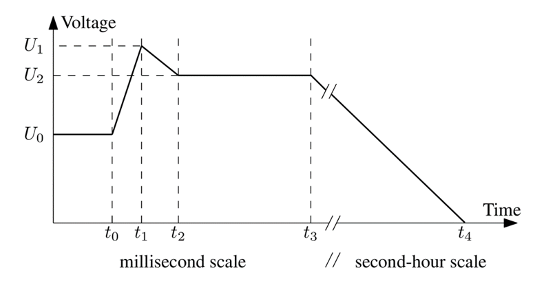
Figure 2 - Proposed DC-LTOV waveshape
This waveshape is characterized by a set of 6 parameters, each depending on the characteristics of the link.
| Name | Simulated / Observed | Major influencing parameters | |
| U1 | Peak voltage | 1.7 - 1.8 p.u. | - Protective level of surge arresters - Cable length - Converter blocking time - AC voltage on transformer valve side |
| U2 | Plateau voltage | 1.5 - 1.6 p.u. (ac/dc side faults) | - Protective level of surge arresters - AC voltage on transformer valve side |
| t1-t0 | Time to peak | 500 µs – 5 ms (based on 50 - 300 km cable) | - Cable length (major impact) - Converter blocking time - Arm and converter transformer reactance |
| t2-t1 | Time of peak decay / first decay | 1 – 60 ms Mostly less than 7 ms (based on 50 - 300 km), but in special cases longer. | - Surge arrester protection scheme (number of parallel columns; SA knee point) - AC breaker opening of one station |
| t3-t1 | Time of plateau (cable discharging plateau) | 100-200 ms | - AC breaker opening time of both stations - Emergency grounding (t4-t2) |
| t4-t3 | Time of plateau (cable discharging plateau) | 30 s for ground switch > 10 min (passive grounding through the converter cell resistances) | - Emergency grounding - Discharging strategy |
This table (and the typical parameter values) have been established following simulations on a symmetric monopolar system.
Although a full parametric study has not been performed for a rigid bipolar configuration, simulations show that the expected voltage levels are very dependent on the earthing strategy but in all cases are considerably lower than for symmetric monopoles.
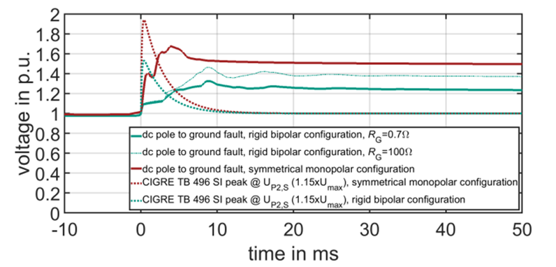
Figure 3 - Example comparison of DC phase-to-ground fault TOVs in a rigid bipole configuration and a symmetric monopolar configuration, representing long cable transmission length >300 km
Regarding mixed systems (with both overhead lines and underground/subsea cables) the brochure concludes that short cable lengths are at risk of very high opposite-polarity lightning overvoltages (possibly over 2.1 p.u.) in case of backflashover on one of the overhead line towers. The protection of such systems must therefore be carefully and specifically evaluated.
Lightning impulse overvoltages in general are highly dependent on project-specific configuration and must therefore be evaluated on a case-by-case basis during the insulation coordination process.
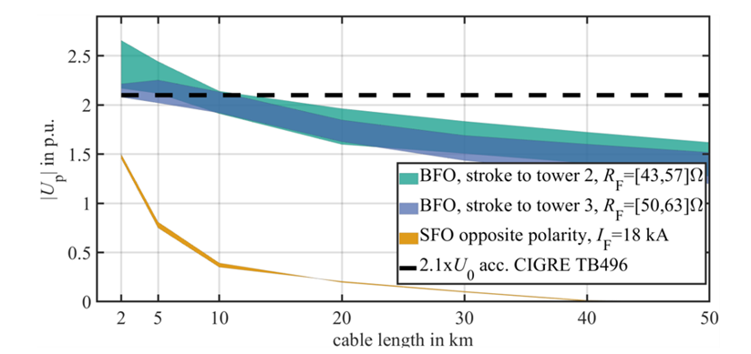
Figure 4 - Absolute maximum opposite polarity lightning overvoltage |UP| along the cable as a function of cable length
DC-LTOV Severity and Insulation Capability
This chapter assesses whether the representative DC-LTOV identified for HVDC VSC cable systems introduces dielectric stresses beyond those already covered by existing qualification recommendations, particularly CIGRE TB 496, CIGRE TB 852, and IEC 62895. The analysis first compares the maximum electric field in extruded cable insulation during the DC-LTOV with the fields occurring during the load cycle type test (LCTT) and the superimposed switching impulse tests of same and opposite polarity. For the studied 320 kV DC-XLPE cable, the DC-LTOV can exceed the LCTT field, especially under hot cable conditions and during the longer plateau interval. However, the same-polarity superimposed switching impulse test, with peak levels between 2.1 and 2.4 p.u., is found to cover the maximum DC-LTOV field in both cold and hot conditions.
ELECTRA, is the digital magazine of CIGRE, you can obtain access as part of a CIGRE membership. Find out more about joining options here.
Other Technical Brochures