Shunt capacitor switching in distribution and transmission systems
The switching devices associated with different loads in distribution and transmission networks have different switching duties to fulfil with sometimes contradicting performance requirements. Thus, a switching device intended to switch reactors might require other abilities than a device to switch capacitors. In this Technical Brochure (TB) the switching of capacitor banks is addressed with the main focus on the applied switching devices, not on the associated equipment such as capacitors, reactors etc.
Convenor
(DE)
E. DULLNI
Secretary
(DE)
C. HEINRICH
R. ALEXANDER (US), B. BAUM (NL), A. BOSMA (SE), D. DESMOND (US), M. KAWADA (JP), M. KLEIMAIER (CH), S. KIM (KR), Z. LIU (CN), S. MÖHL (DE), R. NICOLINI (IT), M. RECKER (DE)
Contributing Members : E. BOYLE (IR), Y. GENG (CN), X. GODECHOT (FR), A. KALYUZHNY (IL), M. MOABELO (ZA), J.A. SANCHEZ (ES), R. SMEETS (NL)
Objectives of this Technical Brochure
Generally speaking, the performance of a capacitor switching device actually required in the field is quite close to its rated and type tested performance and thus poses high stress to the device over the entire life of the equipment. This not only comprises electric stress due to the high recovery voltage, but also mechanical stress due to the large number of operations. The kind of switching device i.e. whether it is based on SF6 gas or vacuum has an impact on the particular physical processes occurring during energizing and deenergizing of capacitor banks and therefore gain special attention in this TB.
The reason to start work on this topic was that 20 years ago the results of CIGRE working group 13.04 initiated a revision of two particular IEC and IEEE standards i.e. IEC 62271-100 and IEEE C37.09 with the implementation of a new extended type test procedure on capacitive switching. The first question was whether this revised procedure really satisfied the expectations of users and improved the performance of switching devices in the field. The second question was whether the testing procedure and parameters still reflect the parameters required in the field.
Contents of the Technical Brochure
The CIGRE WG A3.38, which was formed in 2016, tried to evaluate shunt capacitor switching performance of medium voltage and high voltage switching devices. This was achieved on one side by collecting testing and service experience in distribution and transmission networks by a survey of utilities in multiple countries. On the other side, the state-of-the-art was obtained from an analysis of publications on the performance of capacitor switching devices and own experiments. The survey contained questions on the size of substation and line capacitor banks, the kind of switching devices, typical switching rates and means for controlling inrush currents, maintenance practices and age of equipment. Publications on the performance of switching devices during breaking of capacitive currents were evaluated pertaining to the inrush current parameters during energizing of capacitor banks. One main target of the Working Group was to assess the long-term performance of capacitor switching devices, in particular with respect to the probability of restrikes.
The TB also provides an evaluation of the standards IEC 62271-100 and IEEE C37.09 with respect to test sequences and test parameters such as capacitive current and peak inrush currents. In particular, the effectiveness of the applied accelerated test procedure focusing on minimum arcing times and high inrush currents and their relevance for operation in the field is analyzed. Also, the particularities of synthetic testing are described, which is the only reasonable procedure to test high voltage capacitive switching devices in the laboratory.
For enhancement of the performance of capacitive switching devices, the state-of-the-art of alternative devices is also described in this TB covering controlled switching, pre-insertion resistors and current limiting inductors and the use of semi-conductors. The pros and cons and benefits of such alternative devices are discussed, some of which are known since long and some have been introduced in the last ten years.
One chapter of this TB discusses the peculiarities of filter bank switching. Parameters of filter banks are explained. In comparison to shunt capacitor switching, inrush currents during energizing of a filter bank are much smaller and therefore less demanding for the switching device. Breaking of currents can be more demanding due to the fact, that the recovery voltage is modified by the additional voltage contribution from the inductance and a superposition of a high-frequency transient voltage. This transient is due to the resonance of filter inductances and cable capacitances. The voltage withstand of the switching device during recovery therefore needs special attention.
Main results
The survey on the application and user experience of capacitive switching devices returned 52 responses from utilities in 18 different countries from which only 38 responses provided sufficient data to be evaluated. Each respondent (utility) provided data on three to four voltage ranges so that the survey covers 146 different utility-voltage ranges, from 3.6 kV to 550 kV (Figure 1).
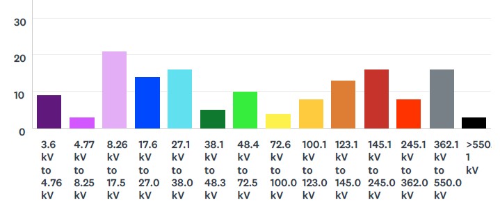
Figure 1 - Number of responses as function of voltage class (range) with respect to substation and line equipment
The survey covered SF6 and vacuum circuit breakers, oil circuit breakers, capacitor and load switches and circuit switchers. It has to be remarked that the resulting occurrences (Figure 2) do not reflect the mean percentage of use in one utility but the percentage of respondents using the indicated switching device.
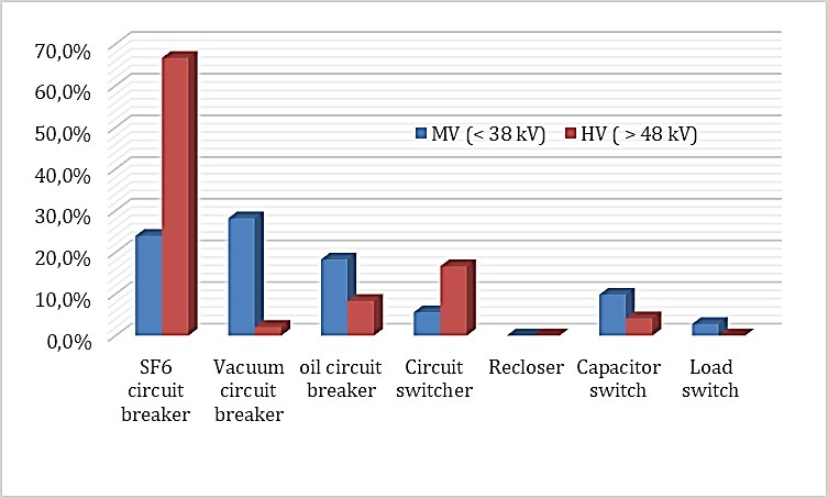
Figure 2 - Percentage of respondents using the indicated type of switching device evaluted separately for MV and HV networks
It is not astonishing that the switching of capacitors attains much attraction since in order to reasonably support the network with respect to voltage and VAR, the rate of switching of the device should be approximately once a day, which is confirmed by Figure 3.
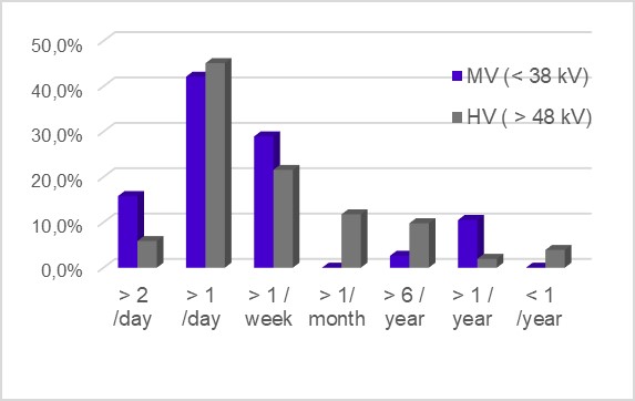
Figure 3 - Responses indicating the typical switching rate for capacitor bank installations agglomerated over medium and high voltage range.
The table summarizes some of the most important questions of the survey and related answers in brief:
| Survey questions | Overall results |
|---|---|
| Why capacitor banks are applied in networks? | The majority applies them for voltage and VAR support. |
| What is the average power of installed capacitor banks? | Capacitive currents at all rated voltages vary between 250 A and 390 A with higher mean current values below 17 kV. |
| Are capacitor banks used on overhead lines? | Only responses from US indicate they are used for this purpose and only at rated voltages up to 38 kV. |
| What is the classification of breakers? | The majority claim class C2 and rarely indicate class C1 or C0 (C0 is only defined by IEEE). |
| What is the rate of switching? | More than 50% of the devices are switched at least once per day. |
| What is the age of the switching equipment? | High voltage equipment is not older than 20 years, whereas medium voltage equipment has an age of 10 to 30 years. |
| What is common maintenance practice? | 89% of the respondents maintain on a time-based schedule with a majority of 47% applying intervals > 5 years in HV networks, whereas in MV networks 42 % claim a one to five years interval. |
| What are causes of failures? | 50% of failures are of dielectric nature occurring in the capacitor bank or in the switching device and 24% are mechanical failures of the switching device. |
| How often surge arresters are used? | Only 33% of the respondents apply surge arresters with a higher percentage in the high end of MV and HV ranges. |
| What is the satisfaction of users with respect to their switching devices? | Satisfaction is expressed mainly for SF6 devices. |
| Are alternative methods applied? | Point-on-wave closing is applied to 60% of all HV breakers, whereas more than 63% do not use any control for MV devices. |
| What are the peak inrush currents? | For MV applications, the majority of inrush currents peak up to 10 kA, whereas for HV peaks even above 20 kA are reached. |
One main purpose of this TB is to give guidance to users for selecting a switching device at the capacitive currents and inrush currents calculated for the capacitor banks used in their distribution and transmission network. These parameters may differ from the switching parameters specified and tested according to the standards. Since the main principles of switching used in today’s switching devices are typically based either on the vacuum or on the SF6 gas technique, the performance of these devices is treated separately in this TB, where appropriate. Other principles are only briefly mentioned. However, the aim of the distinction of the breaking techniques is not to discriminate one against the other but to understand their different performances. Results can be summarized as follows:
Capacitive breaking current
The type tests performed for a rated current of 400 A as specified by the standards are not only valid for currents equal or lower 400 A but also for larger capacitive currents, since higher currents exert a beneficial conditioning effect. This effect is more pronounced for vacuum interrupters, mainly regarding their contact surfaces, than for SF6 interrupters. The Working Group concludes that even significantly higher capacitive currents above the tested value does not change the performance class of the device. A conservative approach may be 50 % higher breaking currents. The breaking performance depends to some degree on the peak inrush currents and the related erosion of contacts.
Inrush current peak
As long as the inrush current peak is smaller than the tested value, it can be assumed that the deterioration of the contact surfaces in a switching operation is smaller than in type tests where the highest inrush current peak (rated value) is applied. In particular, vacuum interrupters show an inverse relationship between peak inrush current and breaking performance. Therefore, peak inrush currents in excess of the rated and tested values cannot be permitted, unless it can be proven that the deterioration of the surface by higher inrush currents is lower than tested, which depends on the inrush frequency. Therefore, a new parameter was introduced i.e. the inrush current integral, ICI, which is an approximate indirect measure of the contact erosion. Figure 4 compares ICI values for back-to-back and single bank switching at different capacitive currents, however, common pre-arc duration and damping factor. Since capacitive current and inrush current peak are preset in Figure 4, inrush frequencies vary between 1400 Hz and even 16800 Hz for back-to-back switching and between 300 Hz and 950 Hz for single bank switching. Under the premises of equal or smaller ICI, the Working Group believes that an extension to higher peak inrush currents might be possible without negative impact on the switching performance. The benefit of alternative devices is to reduce the inrush current peak.
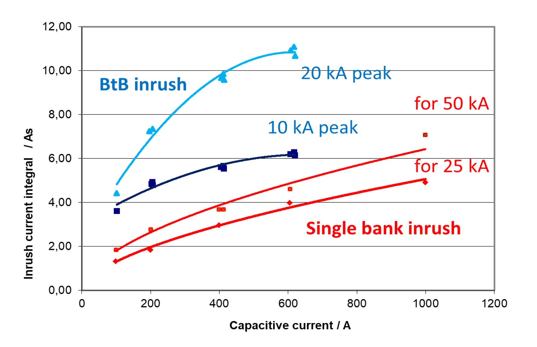
Figure 4 - Inrush current integral (ICI) displayed for different capacitive currents separate for back-to-back switching with inrush peaks of 10 kA and 20 kA (blue lines) and single bank switching with 25 kA or 50 kA rated short-circuit current (red lines); ICI depends on current damping factor (here 0.85) and pre-arc duration (here 1 ms)
Inrush frequency
Except for oil interrupters, the performance of switching devices does not depend on the inrush current frequency. Frequencies considerably above or below the frequency as specified in standards (4250 Hz) can be permitted for vacuum and SF6 interrupters. In any case, the switching of single capacitor banks implies much lower inrush frequencies than for back-to-back capacitors, and the standards do not require separate tests if back-to-back switching has been verified. In order to reduce the inrush current peak and ICI, additional series inductances (reactors) can be installed. This automatically lowers the inrush frequency and has a positive impact on the breaking performance due to the lower inrush current. The frequency specified in the standards is mainly for defining a common test circuit.
Electrical endurance
Based on responses from the survey, the Working Group concludes that the existing type tests according to the standards are an adequate method of evaluating the performance of capacitor bank switching devices. The survey revealed that users are generally satisfied with the performance of their capacitor switching devices. This satisfaction has to be seen in the light that more than fifty percent of the respondents indicate their devices are switched daily, which easily amounts to even more than 1000 operations in a couple of years. This supports the positive assessment of the Working Group that the restrike performance of capacitor switches and circuit breakers tested according to the standards is acceptable in the field or at the very least, if restrikes occur, they are not noticed and therefore are not destructive.
The back-to-back capacitor switching performance verified in 104 three-phase or 168 single-phase attempts according to class C2 per standards IEC 62271-100 and IEEE C37.09 can be extrapolated to at least 500 random operations in the field evaluating the accelerated test procedure applied in the standards. It is probably applicable to a much higher number of operations. Occasionally in experiments, several thousand making and breaking operations were performed. The switching contacts exhibited some deterioration up to severe erosion and melting upon post-test inspection. An impact on the restrike probability could not be determined. Chapter 4 of the TB discusses in detail the specific dependencies determining reignitions and restrikes after current breaking, separate for vacuum and SF6 interrupters. The inrush current characteristic mainly determines the breaking performance among other factors. For vacuum interrupters, where still a lot of open questions on the prevailing physical processes exist, the deterioration of the contacts due to the rupture of microscopic welds from pre-arcs and large-area melting of surfaces due to high inrush currents are essential. For SF6 interrupters, the gradual changing of the geometry of arcing contacts and nozzles due to the erosion of high inrush currents is important.
Conclusion
CIGRE SC A3 keeps the state-of-the-art of switchgear up to date. Readers of this TB will gain a comprehensive understanding of the switching abilities and performance of devices energizing and deenergizing capacitor banks. The peculiarities of vacuum and SF6 interrupters are described and assessed so that users may understand different performances and behavior in service. Guidance is given for users to select switching devices for the specific purpose of single or back-to-back capacitor bank switching in dependence of manufacturer’s specifications and ratings verified in type tests.

Other Technical Brochures