Substation equipment overstress management
The end-of-life considerations for HV equipment are generally based on the equipment’s condition and performance. Another specific aspect of life management is related to the possibility that substation equipment might be subject to predictable/unpredictable system/environmental stresses, what can influence end-of-life decisions.
Convenor
(BR)
A. CARVALHO
Secretary
(BR)
J. AMON
C. LINDNER (CH), R. KARRER (CH), M. HOOIJMANS (NL), M. LACORTE (BR), K. EDWARDS (US), P. MOREAU (FR), S. NKOSI (ZA), S. ANNADURAI (IN)
Corresponding Members : J. OLIVEIRA (BR), A. MERCIER (CA), K. TSUBOI (JP)
For the purposes of the present work, stresses beyond the equipment’s capabilities are classified as overstress and it was the duty of CIGRE Working Group A3. 30 to carry out an investigation to identify practices for detecting and mitigating potential overstresses which might affect substation equipment. The results of WG A3.30 are presented in CIGRE Technical Brochure Substation equipment overstress management and they are summarized in this article.
The traditional approach for end-of-life management asks for permanent follow up of equipment performance, operation conditions and maintenance practices. A robust database on equipment’s life allows asset managers to define performance indicators that are fundamental inputs to identify approaching of end-of-life and thus deciding for refurbishment or replacement [1].
Equipment ageing has also a relevant influence on its performance. However, for this specific topic the CIGRE WG A3.29, “Ageing High Voltage Substation Equipment and Possible Mitigation Techniques”, produced the detailed CIGRE Technical Brochure 725 [2] about ageing process of high voltage substation equipment and recommendations for possible mitigation techniques to manage its performance deterioration.
Ageing is the consequence of the deterioration of equipment’s withstand capabilities, as illustrated in Figure 1. Two mechanisms are generally observed, the normal slow ageing over time or stepwise reduction of withstand caused by faults.
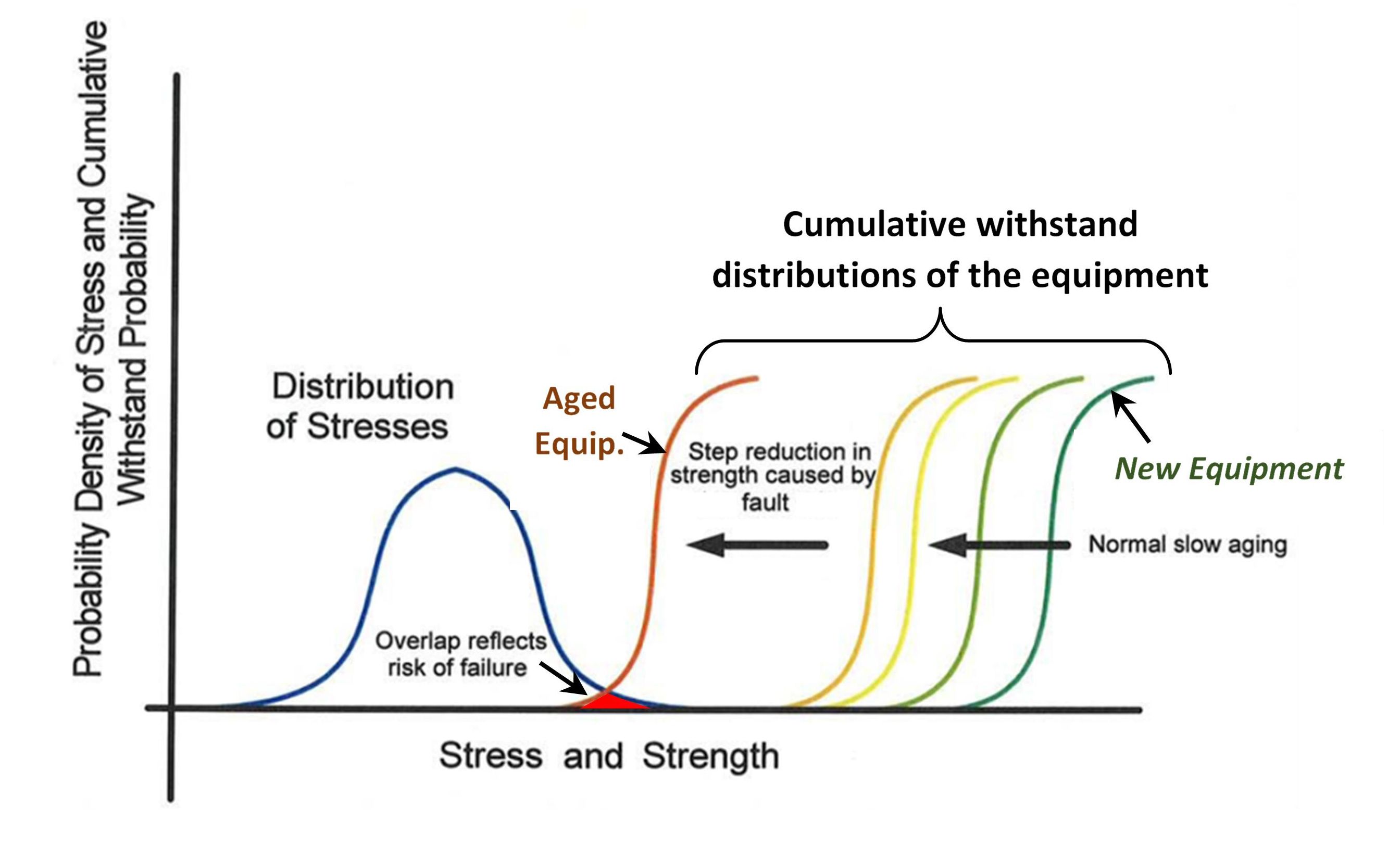
Figure 1 - Equipment risk of failure due to weakening of its strength – Ageing process [1]
Overstresses are stresses beyond HV equipment withstand, as defined in the standards and/or in the specification. The concept of overstress can be well visualized in Figure 2, where the correlation between the statistical distribution of the equipment withstand and the stresses distribution applied to the equipment are presented.
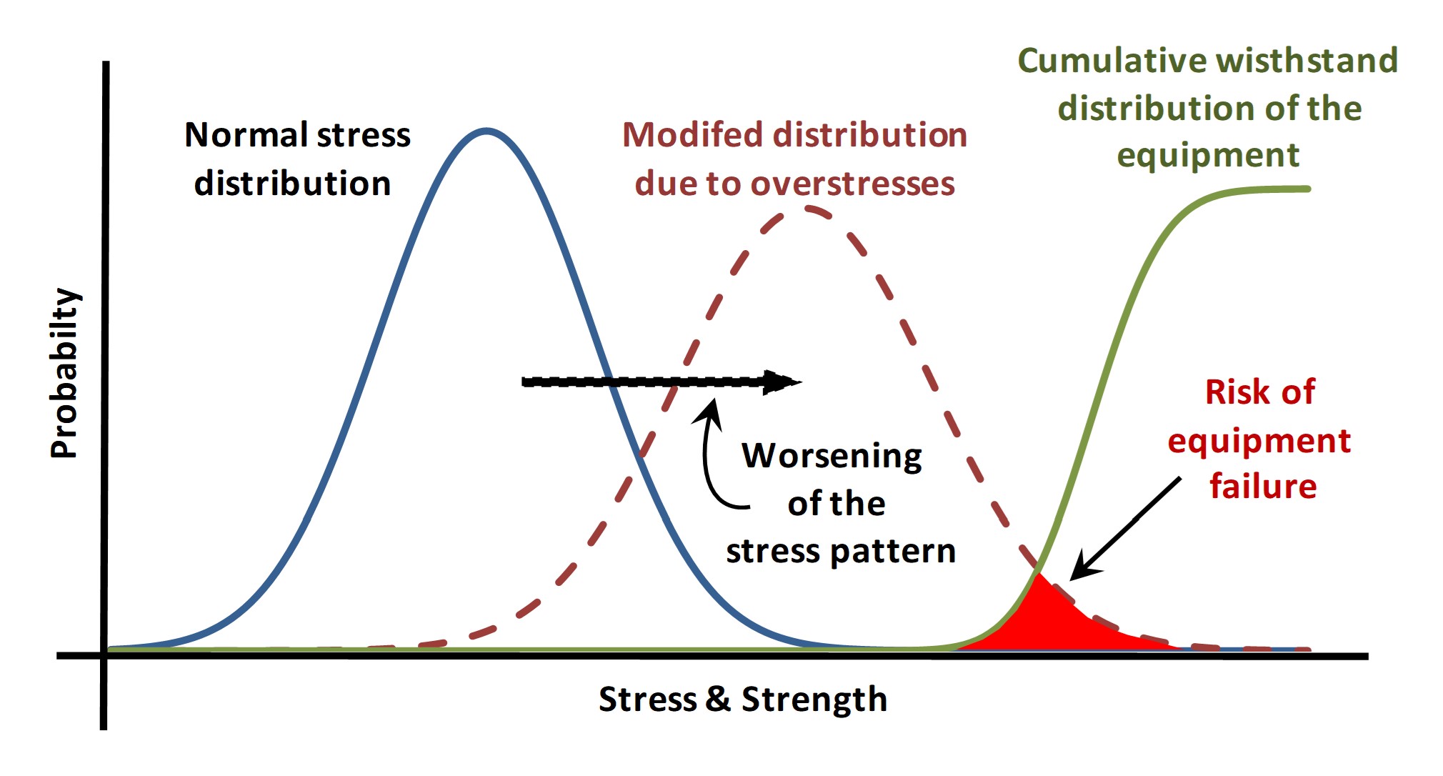
Figure 2 - Equipment risk of failure due to overstresses
Equipment is subjected to overstresses when the stress probability distribution is displaced to the right, thus leading to a relevant risk of equipment failure represented in Figure 2 by the overlap of the externally applied stresses and equipment withstand distribution. In this situation, action must be taken for upgrading, or replacement, or application of mitigation measures [3].
Overstress causes
There are two main kinds of overstresses affecting HV equipment:
- Electrical overstresses originating from the system;
- Environmental overstresses.
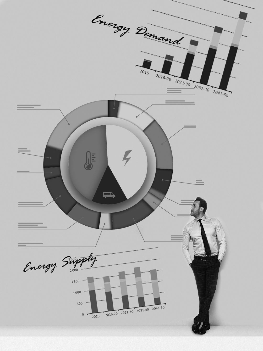
Electrical overstresses originating from the system were traditionally related to capacity expansion [4] before deregulation started in the nineties. At this time, the impact of future overstresses could be clearly identified and was a very strong driver for equipment replacement strategy.
However, in a rapidly changing deregulated environment, where integrated planning of generation, transmission and distribution has been forsaken in favour of market driven planning, overstress management is more challenging than before.
Environmental overstresses can reach levels above standard values and/or equipment specification, such as ambient temperature, lightning, ice, earthquake, etc. Also possible and more frequent are extreme ambient stresses, such as tsunami, flooding, earthquake above 8 Richter scale, etc., which could devastate the electrical equipment [5].
The overstress causes are broadly classified in two main categories, controllable and uncontrollable, as shown in Figure 3. The lowest level of the overstress tree is formed by the primary overstress origin.
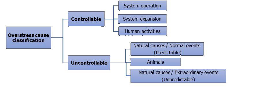
Figure 3 - Classification of overstress causes
Controllable Causes: initiated by human action or system operation measures and strongly related with system operation/expansion and living activities.
Uncontrollable Causes: initiated by natural phenomena. These are further subdivided into predictable and unpredictable causes.
Most of the uncontrollable causes are predictable based on historical data. Beyond standard values the natural phenomena have much lower associated probability. Therefore, they are considered unpredictable and the respective damage can be extreme [6].
Only controllable and uncontrollable but predictable overstress causes can be managed in planning or operation stage. Unpredictable causes are associated to a low risk. Therefore, counter measures generally are not taken to cope with them, unless in very specific situations [7].
Table 1 presets detailed classification of overstress causes based on its origin.
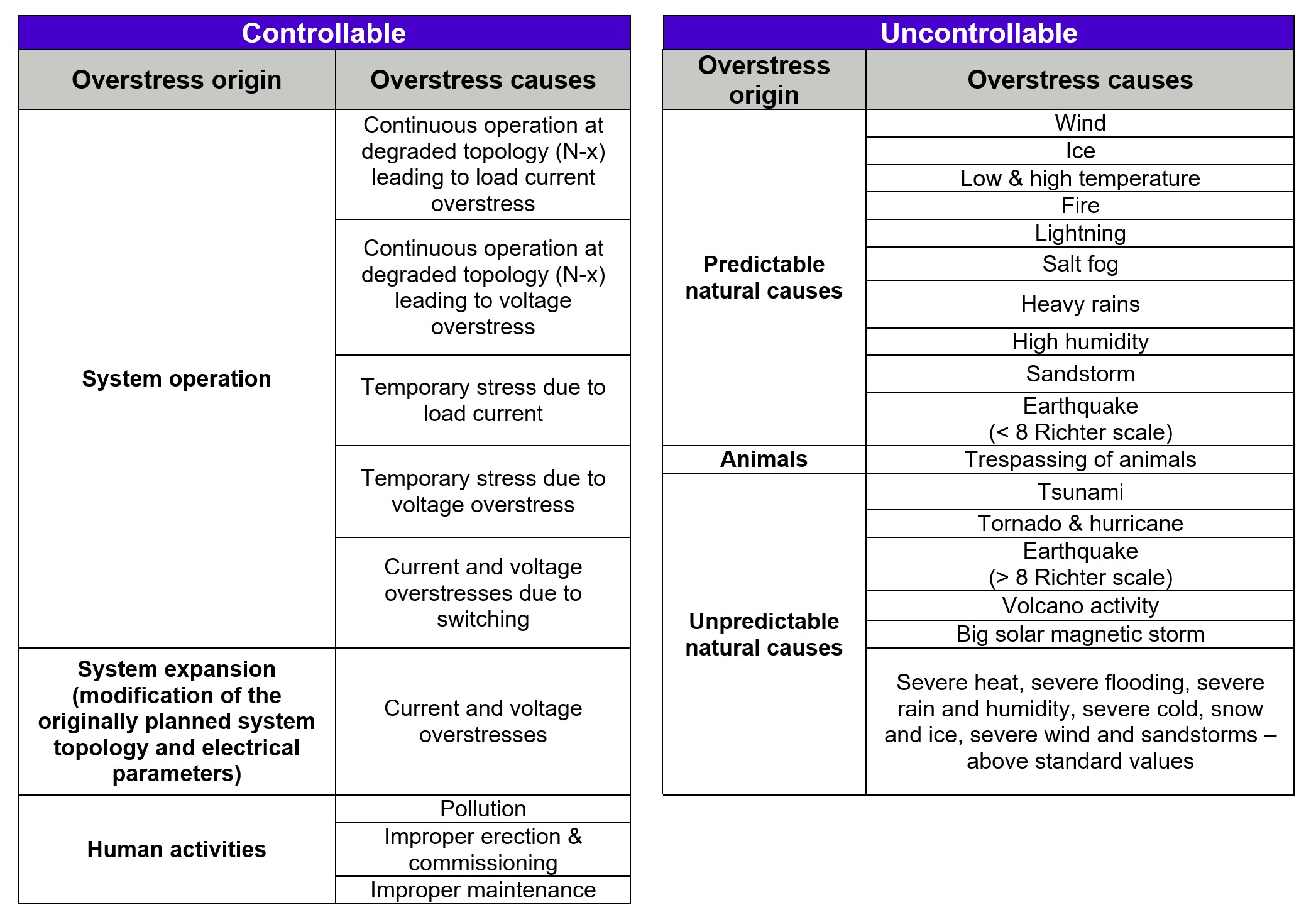
Table 1 - Detailed classification of overstress causes based on its origin
Equipment performance parameters
High voltage equipment performance parameters can be split in four main categories, i.e., electrical, dielectric, mechanical and thermal, as shown in Figure 4. The equipment performance parameters presented in Figure 4 have a direct relation with the withstand ability of HV equipment due to external stresses. In practice, this set of performance parameters are translated into equipment standard requirements, generally IEC or IEEE, which are adopted for the purposes of the overstress analysis.
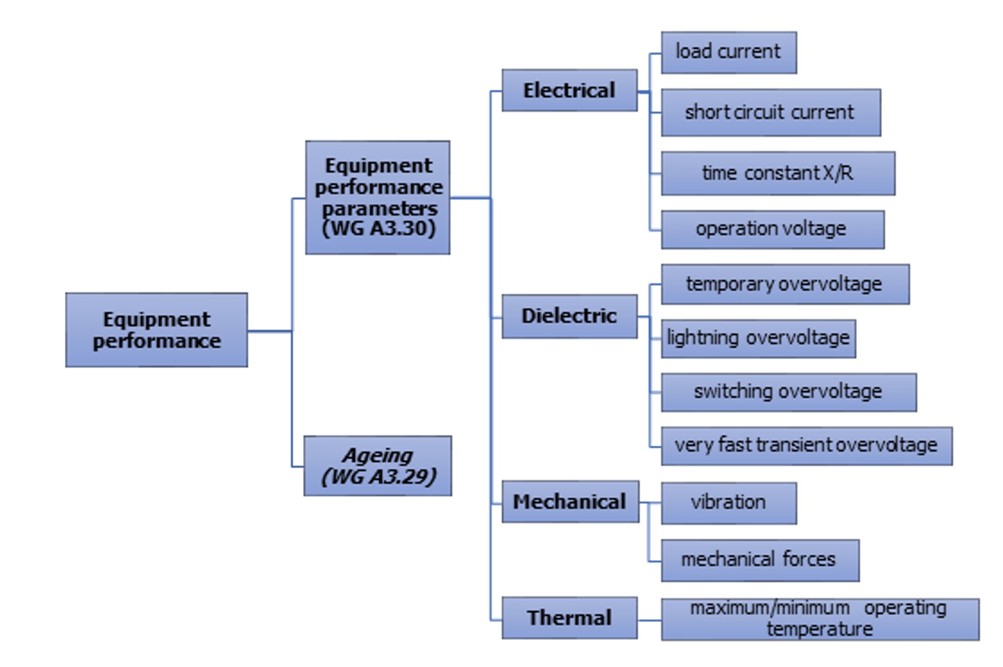
Figure 4 - Classification of HV equipment performance for purpose of Overstresses analysis
A systematic method was applied to prioritize the overstress causes by looking into the possible impact of the overstress to the HV equipment. The well-known Delphi Method [8] was selected as the method for the prioritization of the overstress causes.
For each overstress cause, the frequency of occurrence was estimated, ranging from 1 (never or rarely seen) to 4 (several times a year) and its severity on the component was judged, ranging from 1 (very low) to 5 (complete loss of functionality). The impact of the overstress cause is calculated as the product of Frequency and Severity values:
Impact = Frequency of occurrence x Severity
Each expert of the working group judged the frequency of occurrence (F) and the Severity (S) of the overstress causes to the HV equipment individually and anonymously. By applying the Delphi-Method, the individual answers of the experts were collected, analysed and presented again to the group. The experts which had major deviations or contradictions in the answers had been called for a second round to come up with a common negotiated solution.
The team of experts concluded that a threshold value of 6 would be appropriate for further investigation of the potential overstress causes, but for some of the cases, it was decided in the team to include it in the further investigation because of its relevance to the system operation.
Overstress causes vs. equipment performance parameters
For the most relevant overstresses on the equipment, IEC, IEEE or CIGRE documents were analysed, to check coverage of the equipment performance parameters.
Overstress can be treated in two different horizons, at planning or operation. Nevertheless, it shall be identified early enough to allow any countermeasure before it might affect equipment integrity.
The real time processes consider equipment ratings and maximum operating current and voltage levels to establish operating rules preserving equipment integrity.
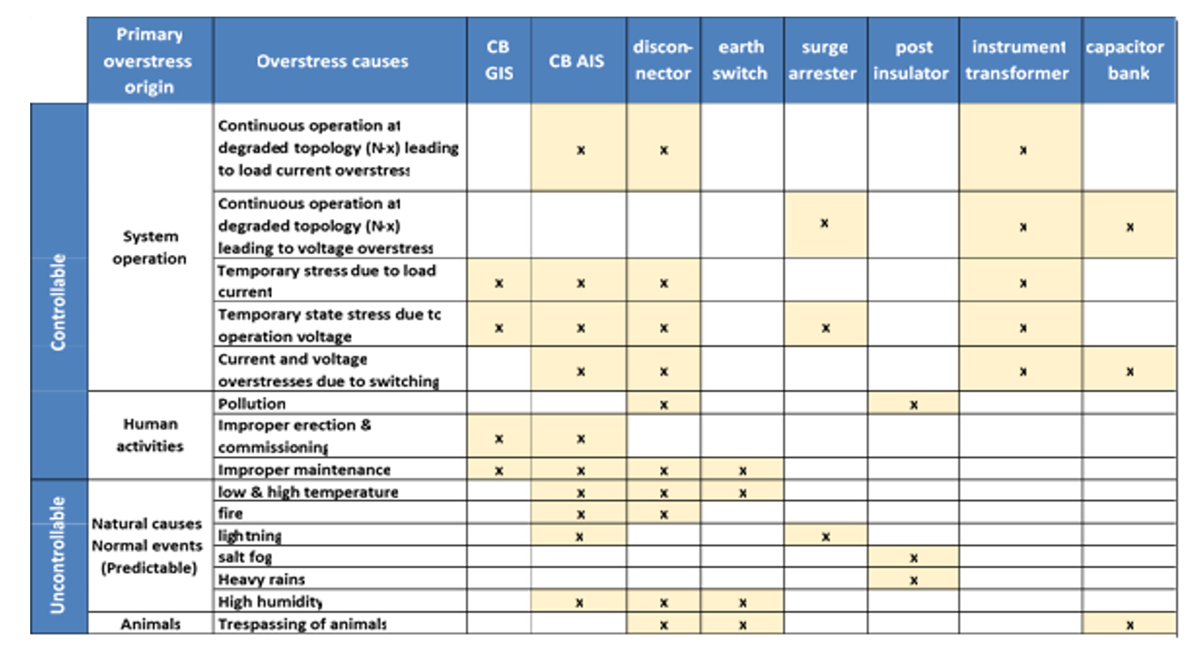
Table 2 - Overview over controllable and uncontrollable overstress causes and their influence on HV equipment
Utilities practices
Two types of electrical overstress analysis are available, the systematic and the non-systematic analysis. The systematic analysis shall be applied with a defined frequency, typically every year or couple of years, depending on utility practices. Table 3 shows performance parameters the equipment considered in the study.
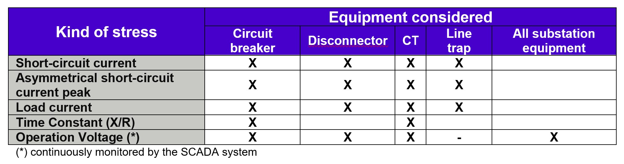
Table 3 – Systematic overstress check on short-term horizon
Non-systematic analysis is carried out only if the utility identifies potential overstress evidences by means of real time operation, monitoring systems or short-term planning studies. The non-systematic analysis checks the equipment specific electrical performance parameters as shown in Table 4.
Conclusions
Overstresses affecting HV substation equipment was the task of CIGRE WG A3.30, whose investigation results are presented in the CIGRE Technical Brochure Substation equipment overstress management. An important step was to develop a proper definition of overstress. According to WG A3.30 overstress is understood as the worsening of the stress patterns imposed to the equipment, whereas the equipment withstand performance remains unchanged. It is assumed that the equipment is well maintained and is not affected by ageing. Influence of ageing is covered by CIGRE TB 725 [9].
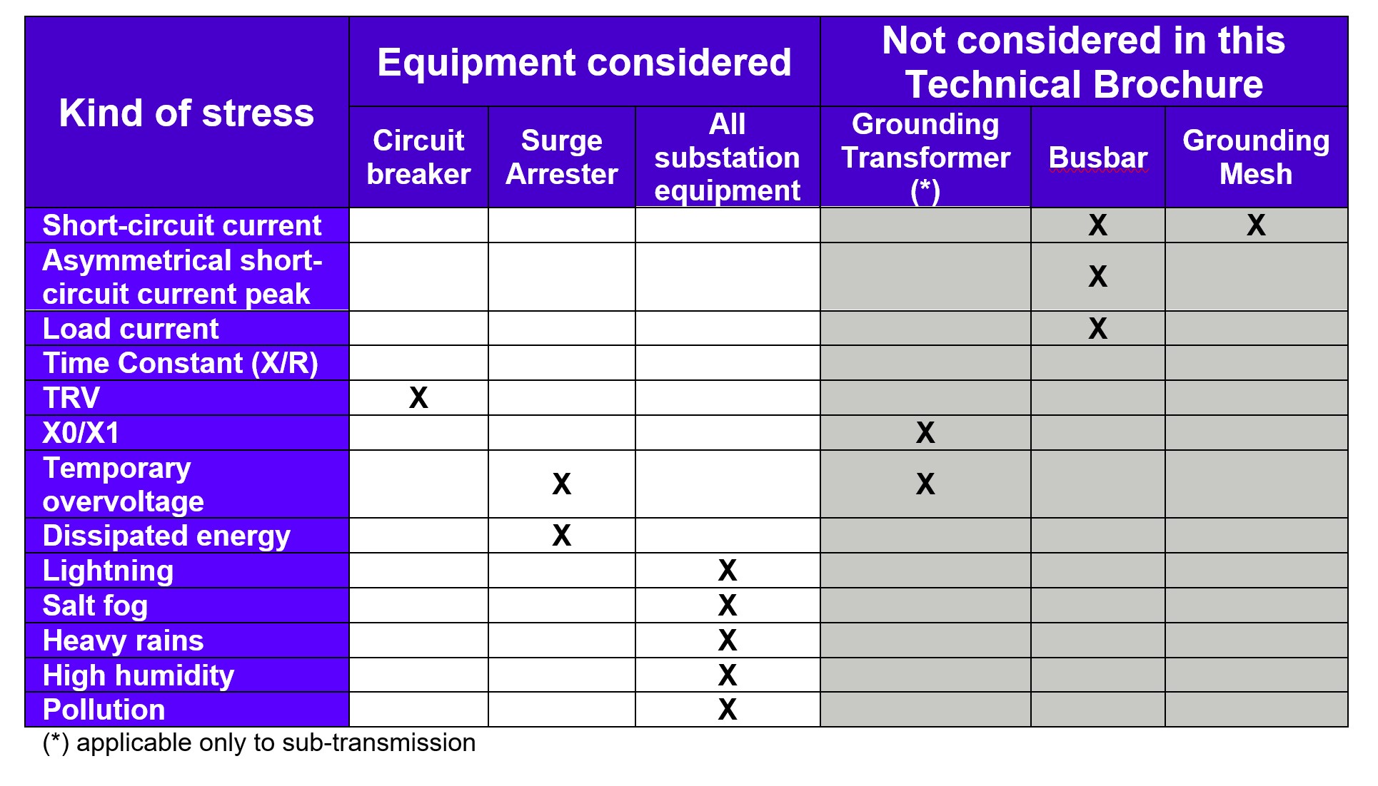
Table 4 – Non-systematic overstress check on short-term horizon
The step-by-step approach adopted to analyse the impact of overstresses to HV substation equipment includes:
- Identification of the overstress causes that might impact equipment performance;
- Selection of relevant equipment performance parameters that can be affected by the overstress;
- Correlation between the two previous set of parameters in order to prioritize the kind of overstress causes that are relevant for each type of equipment considered;
- For each selected overstress cause the coverage of existing standards and/or relevant CIGRE documents were reviewed and discussed for the considered equipment;
- Utilities practices to assess overstresses that might impact equipment performance, as well as discussion of mitigation measures.
Utility needing guidance on how to proceed to manage overstresses affecting HV equipment can make use of the TB by going through the following steps:
- Identify which equipment can be affected by the kind of overstresses considered;
- Check on how the overstress cause affects the specific equipment, the technical standard coverage as well as the relevant technical references;
- Check if there is an identified utility practice to deal with the specific overstress;
- Apply the solution that better fits to solve the specific equipment overstresses case analysed. However, whether replacement, uprating, application of local or system mitigation measures is the optimum solution, this is a question under utility’s responsibility. Economic aspects, regulatory boundary conditions, responsibilities, as well as asset management strategy shall be considered.
Utilities practices to deal with equipment overstress management have a common point: measures are taken to avoid equipment to be submitted to overstresses, since they are generally not designed to withstand it.
The fast changing of network conditions observed because of market liberalization and high penetration of renewables can be considered as the main drives for occurrence of electrical overstresses on HV equipment. As well the changing environmental conditions observed in the last decades are the main source of ambient overstresses
Recommendation for further investigation
The work carried out by WG A3.30 identified some specific overstress causes needing further investigation from technical community in order to give better support to asset managers and system operators. Guidance for standard improvements, including testing methods, commissioning and maintenance procedures are required.
Operation voltage above ratings
A specific electrical overstress of operating at a voltage above the maximum operating voltage values of transmission equipment. This is usually a consequence of the intermittent pattern of renewables generation and the fast growth penetration of this kind of source, including distributed generation at distribution level, as well as the relatively short time for its implementation. This can lead to an insufficiency of voltage regulation resources in the network, thus imposing operation voltages above equipment ratings. This is a topic requiring further investigation, since the actual standards do not cover this operation condition.
Temporary overvoltage withstand ability
A clearer picture on the required ability of HV equipment when submitted to temporary overvoltage stresses is also identified as necessary. The lack of specific testing for this kind of stress, as well as the lack of guidance of equipment standards in defining limits for TOV asks for specific investigation of the technical community on this subject.
Users specify equipment to withstand the electrical and environmental stresses as a function of system topology and geographical location they will be installed. In addition, secondary system solutions can be adopted, like controlled switching or monitoring, to reduce or forecast stresses that might affect HV equipment in order to avoid possible overstresses and their consequences. The response of CIGRE to this kind of overstress was the creation by the end of 2019 of a join working group (JWG) between Study Committees A3, A2, A1, and B1.44 to investigate the “Limitations in Operation of High Voltage Equipment Resulting of Frequent Temporary Overvoltage’s”.
Controlled switching performance
Controlled switching is a mitigation measure for switching transients. However, it has been reported that in some cases its performance in the field is not as planned. The investigation of such problem is under way by CIGRE Working Group A3.35 (Guidelines and Best Practices for Commissioning and Operation of Controlled Switching Projects) and a technical brochure discussing commissioning and maintenance practices for this kind of technic shall point out a set of recommendations and best practices that are of relevance for guaranteeing the performance of controlled switching systems. Among them, commissioning and maintenance practices can be highlighted.
Instrument transformers performance
Recent failures reported for different types of instrument transformers in transmission systems is attracting the attention of specialists. A possibility for these occurrences is overstresses due to unforeseen VFTO caused by compaction of AIS substation arrangements. Therefore, a CIGRE Working Group A3.42 (Failure Analysis and Risk Mitigation for Recent Incidents of AIS Instrument Transformers) was recently created to investigate these occurrences and try to track the possible reasons and propose applicable mitigation solutions.
- [1] [a] CIGRE Technical Brochure 309 (2006), “Asset management of transmission systems and associated CIGRE activities”, WG C1.1, www.e-cigre.org ; [b] CIGRE Technical Brochure 486 (2012), “Integral decision process for substation equipment replacement”, WG B3.06, www.e-cigre.org.
- [2] CIGRE Technical Brochure 725 (2018), “Ageing High Voltage Substation Equipment and Possible Mitigation Techniques”, WG A3.29, www.e-cigre.org
- [3] [a] Carvalho, A.C., Muniz, M., Sinder, D., D’Ajuz, A., “Managing HV equipment replacement due to overrating”, CIGRE Session 2008, paper A3-106, September 2008, Paris. [b] Carvalho, A.C., D’Ajuz, A., Monteiro, A.M., Sinder, D., “Overrating mitigation measures for HV circuit breakers CIGRE SC 13 Colloquium”, paper PS2-10, September 2007, Rio de Janeiro. [c] Carvalho, A.C., Tenorio, R., Waldron M., Escoto M., Lemaitre N., “Criteria for Tracking Transmission Equipment Overstress”, paper A3-207, CIGRE SC A3 Technical Colloquium, 2011, Vienna. [d] Carvalho, A.C., Amon, J.F., Lindner, C. Karrer, R., Moreau, P., Hoijmans, M., Annaudari, S., Nikosi, S., Mercir, A., “Managing Substation Equipment Overstresses”, CIGRE SC A3 Technical Colloquium, paper 103, 2015, Nagoya. [e] Pereira, F. P., Peralta, J. M., Sereno, M. G., Fontes, M. A. P., Amon, J.,” Equipment overrating – transmission companies alternatives to avoid equipment replacement”, XIX SNPTEE, paper SGE 14, 14-17/10/2007, Rio de Janeiro, (in Portuguese). [f] E. Carlini, M.L. Crociani, D. Falorni, A. Freddo, V. Iuliani, E. Colombo, G. Pucci “Upgrading of the short-circuit power of a 380 kV substation: problems to cope and possible solutions in a unified context” CIGRE 2010 Session, paper B3-213.
- [4] Carvalho, A.C., Tenorio, R., Waldron M., Escoto M., Lemaitre N., “Criteria for Tracking Transmission Equipment Overstress”, paper A3-207, CIGRE SC A3 Technical Colloquium, 2011, Vienna
- [5] [a] Ohno, T. Ito, H. Nakakoji, T. Kobayashi, H. Sato, “Study of seismic design and guideline of substation equipment based on the Great East Japan Earthquake”, CIGRE 2014 Session, paper A3-304. [b] H. Miyakawa, H. Takada, Y. Ito, M. Toyoda, J. Kida, H. Koyama, “Investigation of composite insulators in extreme environments – Heavy snow and severe pollution”, CIGRE 2014 Session, paper A3-305. [c] CIGRE Technical Brochure 614 (2015), “Air Insulated Substation Design for Severe Climate Conditions”, WG B3.31, www.e-cigre.org.
- [6] [a] Ohno, T. Ito, H. Nakakoji, T. Kobayashi, H. Sato, “Study of seismic design and guideline of substation equipment based on the Great East Japan Earthquake”, CIGRE 2014 Session, paper A3-304. [b] H. Miyakawa, H. Takada, Y. Ito, M. Toyoda, J. Kida, H. Koyama, “Investigation of composite insulators in extreme environments – Heavy snow and severe pollution”, CIGRE 2014 Session, paper A3-305.
- [7] [a] Ohno, T. Ito, H. Nakakoji, T. Kobayashi, H. Sato, “Study of seismic design and guideline of substation equipment based on the Great East Japan Earthquake”, CIGRE 2014 Session, paper A3-304. [b] H. Miyakawa, H. Takada, Y. Ito, M. Toyoda, J. Kida, H. Koyama, “Investigation of composite insulators in extreme environments – Heavy snow and severe pollution”, CIGRE 2014 Session, paper A3-305.
- [8] Sackman, H., Delphi Assessment: Expert Opinion, Forecasting and Group Process, R-1283-PR, 1974
- [9] [3] CIGRE Technical Brochure 725 (2018), “Ageing High Voltage Substation Equipment and Possible Mitigation Techniques”, WG A3.29, www.e-cigre.org

Other Technical Brochures