Maintenance of HV Cable Systems
Maintenance of high voltage cables and accessories ensure the availability of a cable system during service. Generally, cable systems have an expected lifetime of several decades depending on various factors such as age, insulation type, voltage, and operating history. To ensure the cable system is utilized in a safe and expected manner maintenance of the system is required. This can be achieved through inspection, testing, diagnostics and/or monitoring of the cable system.
Convenor
(BE)
B. Mampaey
Secretary
(NO)
T. Lucignano
C. AHERN (IE), B. BOCHENSKI (CA), J. CHARVET (FR), A. FOSSI (IT), I. JOVANOVIC (US), J. LEVINE (CA), S. RAPOPORT (GB), T. SCHRANK (DE), G. VILLIAS (NL), T. WORZYK (SE), A. AINSLEY (GB), M. CABAU (FR), G. DONOSO (ES), Y. GOTO (JP), P. LEEMANS (BE), A. MACHL (AT), T. SARTO (DK), G. SVEJDA (AT), M. WEBER (CH)
CORRESPONDING MEMBERS: J. FERENCZ (AU), P. HARIPERSAD (SA), B. NOPPORN (TH), T. HERMANS (NL)
Asset managers face challenges related to ageing assets and possible asset replacements. One of the main concerns is to determine how long cable systems can be operated at low maintenance costs while sustaining good reliability. This question is especially important if changes in operational or environmental conditions adversely affect the initial assumptions regarding the expected lifetime, such as higher operating loads or higher soil temperatures. Nevertheless, effective cable maintenance positively affects the lifetime of cable systems. With maintenance and monitoring, certain abnormalities can be detected in the early stage (e.g. fluid leaks, sheath faults, corrosion, partial discharge (PD) screening), allowing repair and avoidance of further damage to the system. These fundamentals of cable maintenance are important in maintaining an operational cable system.
During the 71st CIGRE SC B1 meeting held in Kristiansand (Norway) between August 31 and September 4, 2015 it was decided to set up a task force (TF) on the topic: “To update TB 279 Maintenance for HV cables and Accessories, with the request to advice if it is feasible to set up a WG on the subject".
The TF concluded that there was a clear need for a WG to update TB 279 (which was published in August 2005). The new WG was expected to deal with the following items:
- To collect feedback from utilities on the present situation and future needs by circulating a questionnaire to utilities;
- To make the present TB 279 more complete by including AC submarine cables and DC cables;
- To describe modern methods for condition-based maintenance and to pay attention to new developments;
- To focus on practical cases of maintenance;
- To consider the position of FF cables and their increasing need for maintenance.
All cable types need maintenance activities. This brochure considers maintenance of HV AC and DC cables, with extruded and with lapped (laminated) insulation, for land and for submarine applications including their accessories.
Special attention is paid to the maintenance aspects of fluid-filled cables and accessories to assure high reliability of these cable systems while avoiding negative environmental effects.
Existing maintenance practices
Based upon 74 answers received on a questionnaire, different analyses are made on existin maintenance practices and this for all kind of cable systems; land cable systems, submarine cable systems, fluid-filled cable systems. In addition, questions were raised regarding on-line monitoring, diagnostic measurements and future developments.
| Continent | TSO | DSO | Power Generation | Total |
|---|---|---|---|---|
| Africa | 1 | 0 | 0 | 1 |
| Asia | 10 | 2 | 0 | 12 |
| Europe | 15 | 25 | 4 | 44 |
| North America | 3 | 6 | 0 | 9 |
| Oceania | 4 | 4 | 0 | 8 |
| South America | 0 | 0 | 0 | 0 |
Major conclusions on existing maintenance practices
Land cable systems
Almost all users state that they perform preventive maintenance activities themselves. A high percentage of the users are also able to localize faults using their own resources.
For voltages up to 170kV many of the users perform corrective maintenance activities using own personnel. The majority of the land cable system users have available spare parts or have a spare part policy.
The most popular measure to prevent third party damages to land cable systems is route inspections including marker stones, warning signs etc. Another consistent measure observed on systems up to 420kV is provision of information on cable routes to contractors.
The majority of the users consider these actions highly effective and well established although comments received indicated that the effectiveness strongly depends on the maturity and the willingness of the companies or people executing excavation works.
In addition, mandatory systems where all excavation/digging activities must be announced in advance seem to be a good tool to avoid third party damages.
Besides prevention of third party damages, visual inspections, serving tests, verification of sheath voltage limiters, cleaning of outdoor terminations and hot spot measurements are identified as most common maintenance practices. These actions are mostly considered highly effective and well established.
Submarine cable systems
Nearly half of the users stated that they perform preventive and corrective maintenance activities by themselves. However, this statement must be taken carefully since only a part of the activities may be done internally. For example, in case of corrective maintenance, a user may perform fault location internally but rely on a subcontractor for offshore repairs.
The most applied actions to prevent third party damages are:
- inspections of cable routes, burial depth and landfalls,
- use of administrative procedures to provide information on cable routes to contractors.
These actions are mostly considered highly effective and well established. There are also fewer common actions performed by a minority of users such as dialogue with locals (fishermen) and monitoring of fishing and shipping activities in the vicinity of cables.
The main actions for ensuring cable availability (health) which are performed, sorted by decreasing occurrence are:
- continuous temperature monitoring via optical fibre (DTS),
- monitoring of seabed mobility (moving sand waves, seabed erosion),
- inspection for corrosion (cable hang-off on a platform),
- control on free-spans,
- TDR (or FDR or similar) measurements, occasional temperature measurements,
- scour control at I/J tubes.
Those actions are generally considered highly effective and well established, except for TDR and DTS where majority of users would like to see it improved.
Fluid filled cable system
Fluid filled power cables and accessories feature insulation system composed of fluid-impregnated paper or paper/film laminates.
They are generally divided into Self-Contained Fluid Filled (SCFF) and High Pressure Fluid Filled (Pipe-type) cable systems (HPFF or HPGF/GP).
Both systems have ancillary equipment such as reservoirs, pumping stations, pressure gauges and alarms that require periodic maintenance. Fluid filled cable system have been around for a long time and still represent significant installed transmission network base in many parts of the world. In general, these cable systems (mainly the cables themselves) are still in a good condition and the main issue of the technology is the potential for the leak of the fluid which can be accompanied with moisture ingress. Almost all pressurised fluid filled cable systems have a pressure monitoring system with a continuous or periodic maintenance program.
From the replies received on the questionnaire, 67% of the respondents still have fluid-filled cable systems in service. The majority of users have a replacement policy in place or are phasing out the fluid-filled cable systems. About 20 % do not have a replacement policy in place.
The maintenance programs for this type of cables are quite mature, due to the long history and experience. Feedback received via the questionnaire shows that the specific and additional maintenance activities as identified in the questionnaire are considered as very effective and mature, some lower scores were given to the inspection of oil tanks, pump stations and pressure gauge calibration. Also, the dielectric and moisture test on cable fluids scored somewhat lower.
On the other hand, the maintenance on FF cable systems is quite labour intensive compared to newer cable systems such as cable systems with extruded insulation, which do not have tanks with fluid or gaseous insulation under pressure (except for some sealing ends/terminations).
The most recent modifications in the maintenance activities related to FF cable systems consist reduction of the labour part. Some examples are:
- Online fluid pressure monitoring instead of on the spot pressure readings
- Use of tracers in cable fluid to facilitate and speed-up localization of cable fluid leakage
Monitoring and diagnostics
With the purpose of achieving a larger degree of utilization of the cable assets and gaining more meaningful insights in the asset's conditions, monitoring and diagnostic techniques are becoming more and more popular among system operators and utilities. Additionally, recent technological advancement and enhanced big data analytics capabilities have made some of these techniques more powerful, more readily available and more economically viable.
Examples of modern techniques which are gaining ground in the field of on-line monitoring are the Distributed Temperature Sensing (DTS) and Distributed Acoustic Sensing (DAS) (require optical fibre), and Partial Discharge (PD) monitoring. Next to that, a plethora of diagnostic measurements and tests are available for the determination of the condition of an asset. Oil Analysis, serving tests and spot Partial Discharge measurements are examples of diagnostics that are high on the preference list of the asset owners.
A comprehensive group of state-of-the-art monitoring and diagnostic techniques is therefore listed and categorized (monitoring, diagnostic, or both). The applicability of the test technique to a certain type of cable (together with indicative information on the related price level) is provided in a separate chapter in the technical brochure. The test techniques are further shortly explained and the practical application of the techniques to the maintenance of cable systems is also provided.
Future developments
The users of HV cable assets expressed the need for further developments, both of technology and methods that would provide valuable information about cable system condition.
The market availability of different kind of sensors and monitoring devices provide the asset owners with the tools needed to make a full transition towards Condition Based Maintenance (CBM).
At the same time, suppliers and technical engineering companies are going to face an increasing market need for more accurate diagnosis of insulation deterioration and less expensive sensors.
The asset owners may have to implement automated processes for the proper data collection from the field into their asset management systems. In many cases specific software is already present, but new storage techniques, newly developed algorithms, improved automatic analysis and assessment are commonly identified as an area for improvement.
Maintenance Strategies
Maintenance is performed on high voltage equipment for a variety of reasons. The main reasons for carrying out maintenance are:
- To avoid failures
- To avoid environmental damage
- To avoid more expensive maintenance later
- To extend the life of the equipment
- To avoid unsafe situations
- To repair failed components
- To avoid legal and financial penalties
There are three fundamentally different ways to carry out maintenance:
- Corrective maintenance (CM), to repair or replace broken items
- Time-based maintenance (TBM), to perform preventive maintenance based on a specified predetermined schedule
- Condition based maintenance (CBM), to perform preventive maintenance based on the present condition of the component (condition assessment)
TBM and CBM both have the intention to avoid failures in service. CBM can also be called “Predictive Maintenance”, meaning maintenance to be carried out to determine which maintenance actions will follow in order to avoid failures in service.
A next step in maintenance is the probabilistic approach. This method takes into account several parameters, such as asset condition, maintenance costs, importance of the asset, or risks. All these parameters will lead to a probabilistic maintenance program. Needless to say, that in order to be able to build-up such a probabilistic maintenance program, accurate and reliable data and good expert analyses are required.
Based upon the replies received on the survey, we see that up untill today the majority of the maintenance activities performed are still time-based. However, due to the increased number of cable systems being installed worldwide, there is a growing awareness that the maintenance should shift towards more condition-based maintenance.
Performing the traditional TBM on an increasing number of cable systems demands much more effort from an organizational point of view and also demands more personnel to perform these TBM activities, all resulting in increasing operational expenditures (OPEX). On the other hand, utilities are often confronted to limit or even reduce OPEX costs, meaning that the traditional TBM maintenance activities have to be reviewed.
Some trends that we see are the following:
- Modified TBM activities depending on the age, importance or criticality and type of the cable system,
- Reduce the number of TBM activities and include more CBM activities
For the transition to CBM, it is important that all data related to cable systems is correct and kept up to date (repairs, re-routing, etc.). A good historical database of past events/incidents and diagnostic measurements performed is also very important.
An increased interest and application of online monitoring techniques have also been identified during the survey. This also with the intention to replace TBM activities or to give additional input for CBM activities.
Maintenance on HV Cable Systems
For the different type of cable systems (Land, Submarine, Fluid filled), different maintenance activities are elaborated. Both for HVAC and HVDC cable systems.
Many maintenance activities are applicable to both AC and DC land cable systems. However, some specific maintenance activities are required for submarine cable systems.
The topics that are covered are:
- Maintenance activities to prevent third party damage
- Maintenance on the cable itself
- Maintenance on accessories
- Diagnostic measurements
- On-line monitoring
- Special bonded systems
- Cable systems in tunnels
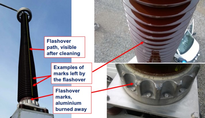
Figure 1 - Visible flashover marks on termination
For submarine cable systems some additional topics are covered:
- Offshore surveys
- Landfall inspections
- Inspections on offshore platforms
- Mechanical protections
- Curative maintenance on offshore cables
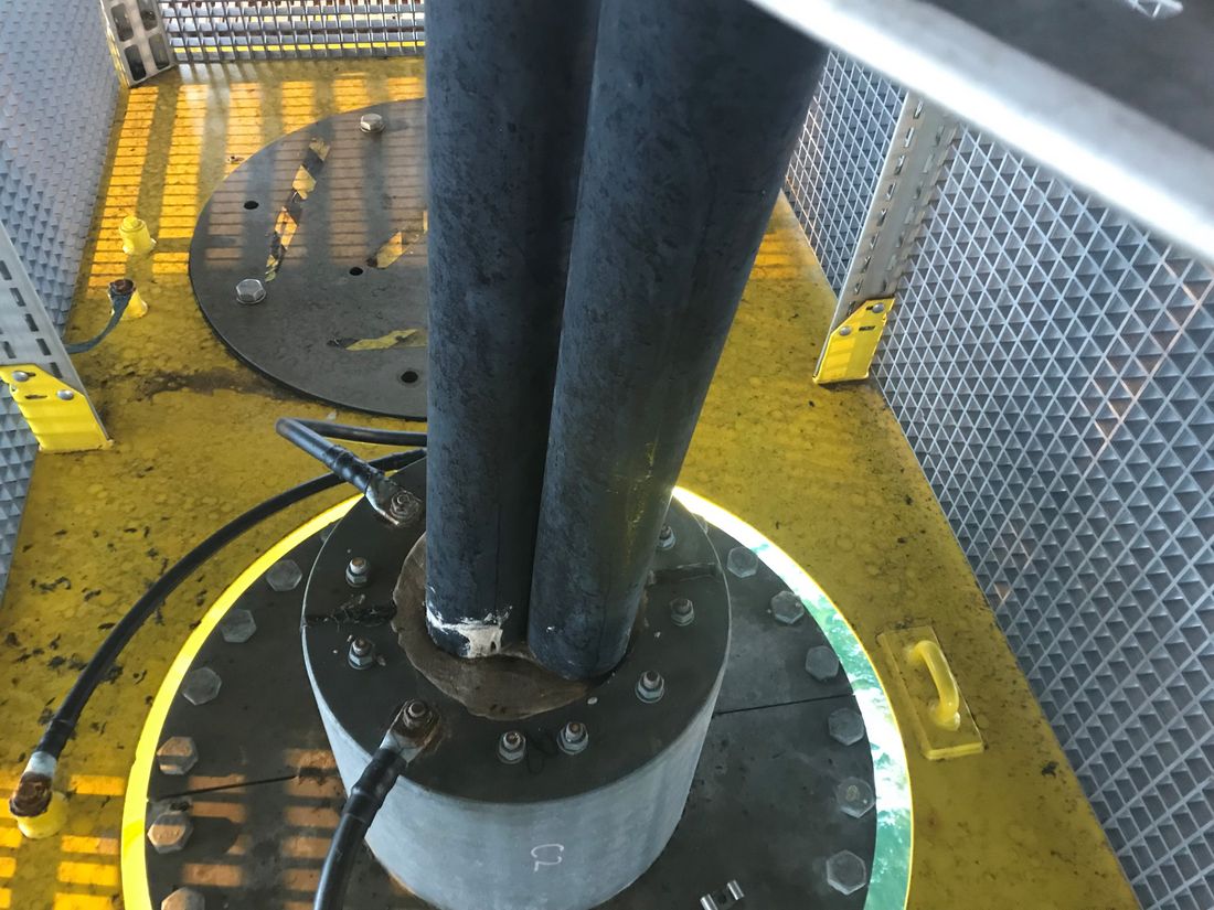
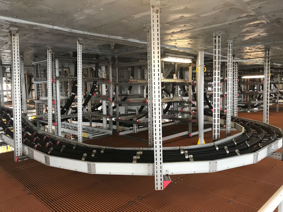
Figure 2 - Hang-off and cable routing on offshore platform
Fluid-filled cable requires also some specific maintenance actions related to the hydraulic system that is needed to maintain this type of cable system.
Furthermore, the current position of fluid-filled cables is discussed based upon the replies received to the questionnaire.
Some alternative fluid leak detection methods are described, such as PFT tracers and the use of dogs. The classical methods are good, but are time consuming, some alternatives exist. Figure 4 shows the freezing of a fluid filled SCFF cable which is applied for fluid leak detection and curative maintenance actions on SCFF cable systems.
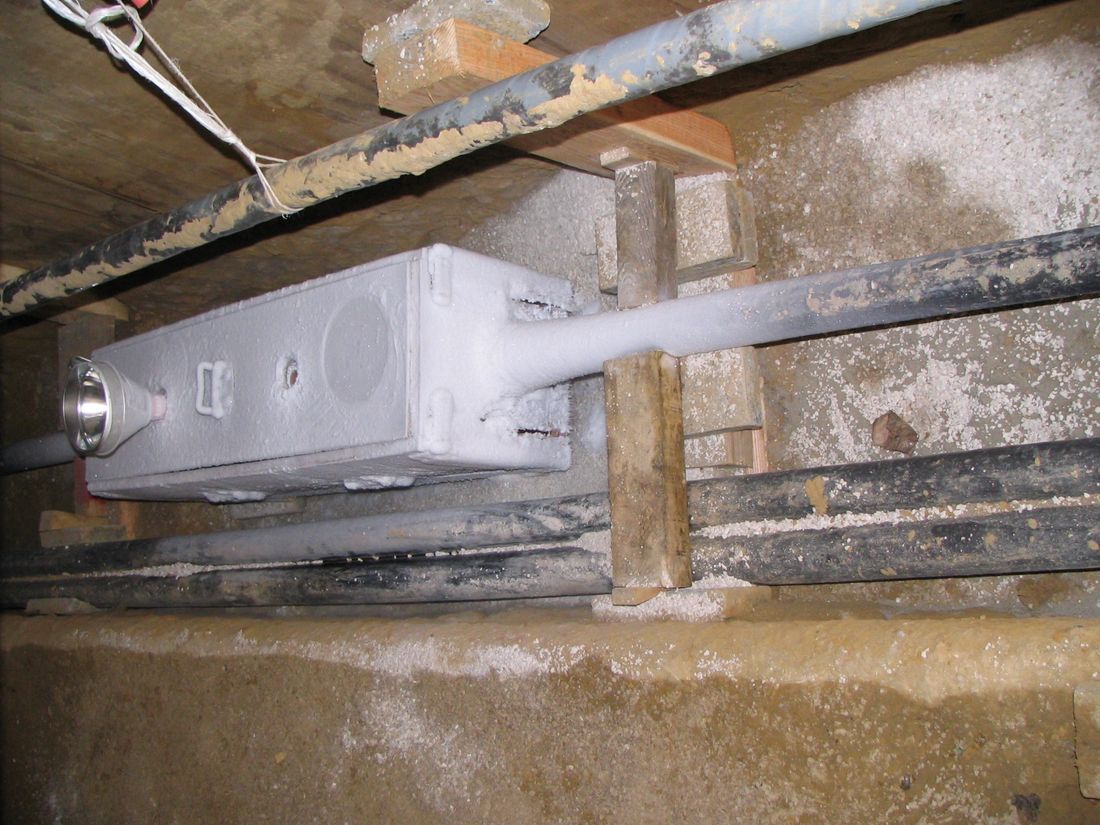
Figure 3 - Freezing of SCFF cable
A case study regarding X-ray images used on fluid-filled cable systems shows the advantages of these technique for determine the repair needed.
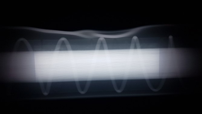
Figure 4 - X-ray on pipe type fluid cable system
Monitoring and diagnostics
Throughout this brochure: a diagnostic technique is one that helps identify the presence, nature and/or cause of a problem within the cable system, typically without specifying how the problem originated; a monitoring technique is intended as a continuous supervision activity carried out by specialized equipment to keep track of specific (critical) parameters during the operation of the asset.
Table 2 gives an overview of the most effective diagnostic measurements based upon the replies received on the questionnaire, 66 of the 74 answers in total.
| Condition Determination maesurements | # users | % |
|---|---|---|
| Oil analysis fluid filled cable and /or accessories | 23 | 35 |
| Checks on earthing and bonding system, serving test, screen currents | 21 | 32 |
| On-line monitoring methods (temperature, PD, etc) | 16 | 24 |
| Partial discharge monitoring/ spot measurement | 15 | 23 |
| No measurements taken | 15 | 23 |
| Temperature measurements (distributed/ spot) | 14 | 21 |
| Oil pressure & oil volume monitoring and readings | 10 | 15 |
| Visual inspections and surveys | 10 | 15 |
| Tan delta measurement | 8 | 12 |
| Time domain reflectometry and/or FDR | 5 | 8 |
| Depth of Burial | 2 | 3 |
| X-Rays test | 2 | 3 |
| Water Treeing occurrence test | 2 | 3 |
| Laboratory tests on cable sample; condition assessment | 1 | 2 |
Furthermore the Technical Brochure provides an overview of the diagnostic techniques applicable to high voltage cables. This overview differentiates the applicable techniques for AC and DC systems, Land and submarine cables, as well as the insulation material of the cable system. An indication of price level is also given in this overview, however some wide range are often given since the length of the cable system can have an important impact on the cost level.
The different monitoring and diagnostics methods are described further in detail in the Technical Brochure.
Spare part management, emergency preparedness and training
Spare part Management
Spare part management aims at increasing the availability of the cable system in operation. To achieve this, a certain amount of spare parts should already be available at the time of commissioning and should be kept ready for use as long as the cable systems for which it is aimed at are under operation. Therefore, spare parts need to be checked, stored and maintained accordingly. In case of use of spare parts, new spares may have to be ordered, depending on what is left is sufficient or not to cover potential future failures.
A proper identification of the critical spare parts to be kept available should take into consideration the combination of three main factors:
- Component failure rate;
- Impact on the quality of service;
- Delivery times (lead times).
Since lead times for the HV equipment are usually not compatible with the needs of a proper continuity of service, this could be considered an irrelevant factor and the choice is determined only by the variability of the first two. For the purpose of identifying the components for which it is appropriate to have stock, these two factors can be related to each other with a law of the type described below:
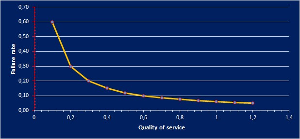
Figure 5 - Failure rate / Quality of service
Emergency Preparedness Plan
Land-based interconnectors and the majority of Submarine power cables represent critical transmission infrastructure as they are significant social and economic connectors. Traditional uses for submarine power cables have been to interconnect island communities to mainland energy networks to reduce the reliance of island communities on power generated by fossil fuels or to transfer remote abundant under-utilised energy to energy starved regions. If the use of this infrastructure is lost it can have a catastrophic impact on interconnected communities, and repair campaigns can take many months depending on location.
While a faulty underground cable often sits in a meshed grid and the power flow can be re-dispatched over other branches of the grid, submarine power cables are less likely to form meshed networks. Nevertheless, in case of a failure for both underground and submarine cable systems short downtimes are desired. Therefore, it is recommended to have Emergency/Repair Preparedness Plan (EPP resp. RPP) in place covering a variety of possible failure scenarios.
A RPP can reduce the impact caused by a cable failure. A short repair time may reduce the economic impact (e.g. loss of income) on the cable operator and the communities they support.
Questions that the cable owner/operator may face upon a cable failure
Directly after cable damage the cable operator faces these questions (and probably even more):
- Where is the failure?
- Do we have spare cable and repair joints? Are the spares in useful condition?
- Where can we hire a repair vessel? What type of vessel and equipment is needed?
- Where can we hire an experienced repair crew including jointers?
- Which permits do we need?
- Which authorities must be informed?
- Who caused the failure, and can we claim compensation?
- Are there crossings of third parties affected by the repair operations? Do we have operation agreements with them?
- Is the damaged cable SCFF type? If yes, it is necessary to urgently activate a contingency plan to mitigate the impact in the environment.
A lack of useful spares can delay the repair seriously since most of the HVAC cables, HVDC cables and submarine power cables are not on stock and need to be re-manufactured by a specific manufacturer. The same issues for HV accessories. It is obvious that the repair time can be shortened if these questions can be answered swiftly. A responsible cable owner/operator would have solved most issues before any failure occurs, except the exact position of the failure. The list given above is a general summary.
Skilled personnel and training
The quality and the performance of newly installed or repaired cable systems are highly dependent on the skills and competences of the jointers who carry out the assembly works of joints and terminations. Continuous and thorough training is important to maintain and improve skills related to the assembly work. Usually, the custom-made training courses and certification procedures are offered from the manufacturer of the accessories or certified institutes collaborating with the manufacturers.
Cost of maintenance
In general, cable systems are assets that needs limited maintenance, however some differences exist between different types of cable systems (e.g. fluid filled cable systems compared to extruded cable systems).
The maintenance cost can be split in the following subgroups:
- Labour costs - number of FTE's to perform preventive maintenance
- Monitoring and measurements
- Offshore surveys
- Repair costs
- Service Level Agreement costs (e.g. with external companies committed to provide repair services in case of cable failure)
- Costs of storage and maintaining spare parts in operational conditions
The general trend is to control the maintenance costs and especially the number of FTE's to perform the required maintenance activities. An optimum must be found between preventive maintenance costs and curative maintenance costs. Reducing preventive maintenance cost can increase the curative maintenance cost. A good balance must be found between both to have an optimal total maintenance cost.
Besides the total maintenance costs from financial point of view, also the availability, reliability of the network and reputation of the asset owner must be taken into account.
Maintenance and remaining life
Generally, cable systems have an expected lifetime of several decades (ie. 40 to 65 years for land cables). The exact lifetime of cable systems however depends on various factors. Relevant factors are inter alia operating and environmental conditions and corresponding design criteria (e.g. insulation and overvoltage requirements, thermo-mechanical forces), insulation type, voltage rating, overall quality of components and workmanship during laying and installation as well as potential third party impacts. During the service period, cable systems are constantly subject to effects of aging and wear (especially due to high loads, switching actions and transients).
Asset managers face challenges related to aging assets and upcoming replacements. One of the main concerns is to determine how long cable systems can be operated at low maintenance cost while sustaining good reliability. This question is especially important if changes in operational or environmental conditions adversely affect the initial assumptions regarding expected lifetime (e.g. higher loads or higher soil temperatures).
Nevertheless, proper cable maintenance positively affects lifetime of cable systems.
With maintenance and monitoring certain abnormalities can be detected in an early stage (e.g. fluid leaks, sheath faults, corrosion, PD screening, abnormal temperatures), which eases repair and avoids bigger damages.
Topics like criteria for end of life, failure rate calculation, health index and retirement strategies are described further in the technical Brochure.
Future developments
In the context of this brochure future developments are to be considered the improvements that the currently available cable maintenance technology needs to acquire in order to get from experimental applications to a widespread use. These new technologies, whenever clustered around a common strategic vision, can generally be grouped in technical vectors that, if correctly developed, could reshape the HV cable maintenance in the near future.
The Technical Brochure gives an overview of the needs identified by the responders based on some open questions raised.
Case studies
Some practical case studies are included in the Technical Brochure covering the following topics:
- Cable Terminations endoscopy
- Distributed Temperature Sensing on submarine cable systems
- Extending asset life
- Fluid Filled cable leak detection
- Outer damage sensor on a submarine cable
- Screen current monitoring
- X-Ray
- Gamma Ray
- Replacement of SCFF cable segment
- Cathodic protection (and stray currents) monitoring
- Fluid Oil Compensation System
Analysis questionnaire
A detailed analysis of the replies received on the questionnaire is added as an appendix to the Technical Brochure.
This is based on 74 replies received and the results are detailed for:
- Land cable systems (AC and DC)
- Submarine cable systems (AC and DC)
- Fluid-filled cable systems

Other Technical Brochures