Challenges with series compensation applications in power systems when overcompensating lines
Series compensation is a cost-efficient way to decrease the line reactance and improve the system stability and increase the transfer capacity for long transmission lines. Traditionally, the maximum degree of compensation has been around 80 %. The necessity to connect renewable electricity sources (e.g. wind and solar power stations) is a driver for installing new substations along series compensated lines. When a new substation is installed along an existing series compensated transmission line, the result can be an overcompensated line, i.e. a line, which has an effective series reactance that becomes capacitive.
Convenor
(FI)
L. HAARLA
Secretary
(FI)
A. HARJULA
P. DATKA (US), H. ERIKSSON (SE), M. MCVEY (US), K. NARENDRA (CA), S. SRIVASTAVA (IN), A. TAYLOR (UK), Z. BIN (CN), R. LE ROUX (IE)
Introduction
At least one overcompensated 400 kV line exists and it is located between Sweden and Finland [1]. Originally the cross-border line was series compensated in 1997 with a compensation degree of about 70 %. Adding a new substation along the line in 2016 created a 140 % compensated line as Figure 1 shows.
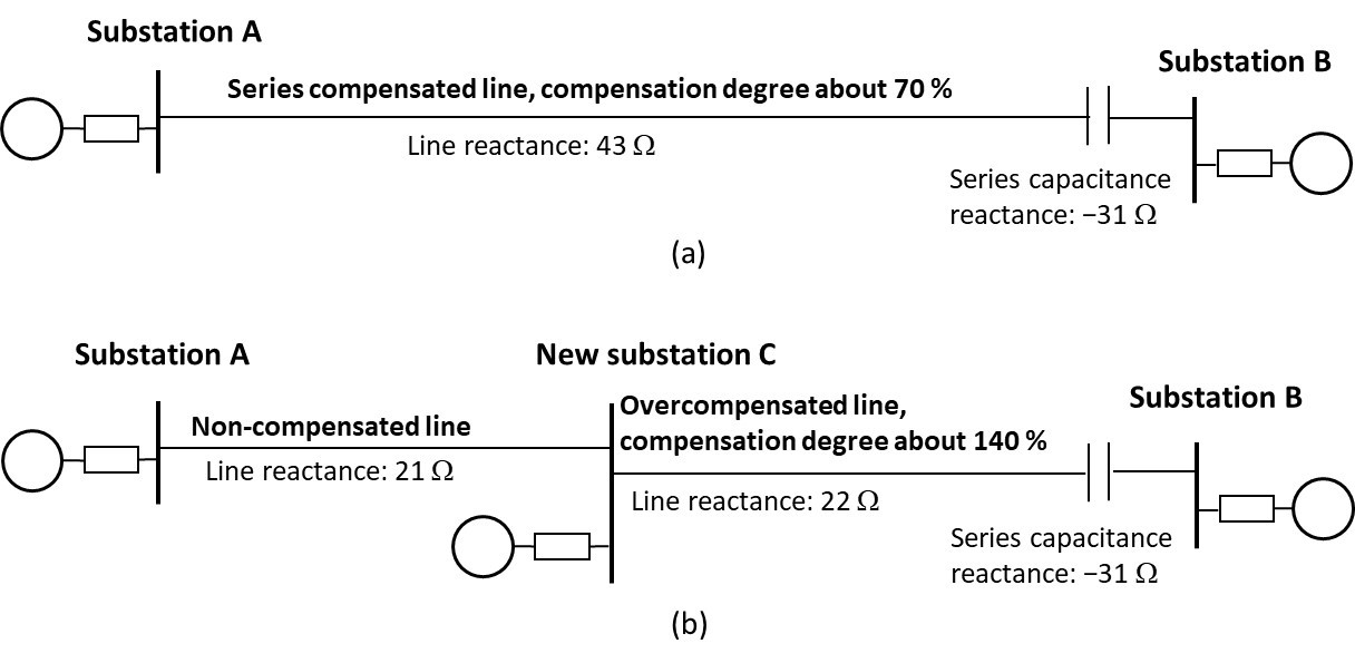
Figure 1 - Figure (a) shows the series compensated cross-border line between Finland and Sweden. Figure (b) shows how adding a new substation in 2016 along the series compensated line created an overcompensated line C–B
There is a lack of literature available addressing how overcompensated lines affect power system phenomena such as steady state and dynamic voltages, resonances, transient overvoltages, transient recovery voltages of line circuit breakers and the protection of overcompensated and their adjacent lines. There is literature on these topics for systems having normal compensation degrees: 40–80 %.
The Technical Brochure (TB) also covers traditional compensation degrees of a series compensated line, which has an overcompensated line segment, even when the effective reactance of the total line would be inductive. An overcompensated line segment is the location along the line near the series capacitor where adding a substation would create an overcompensated line. Figure 2 shows overcompensated line segments for three series capacitor locations with 70 % compensation degree.
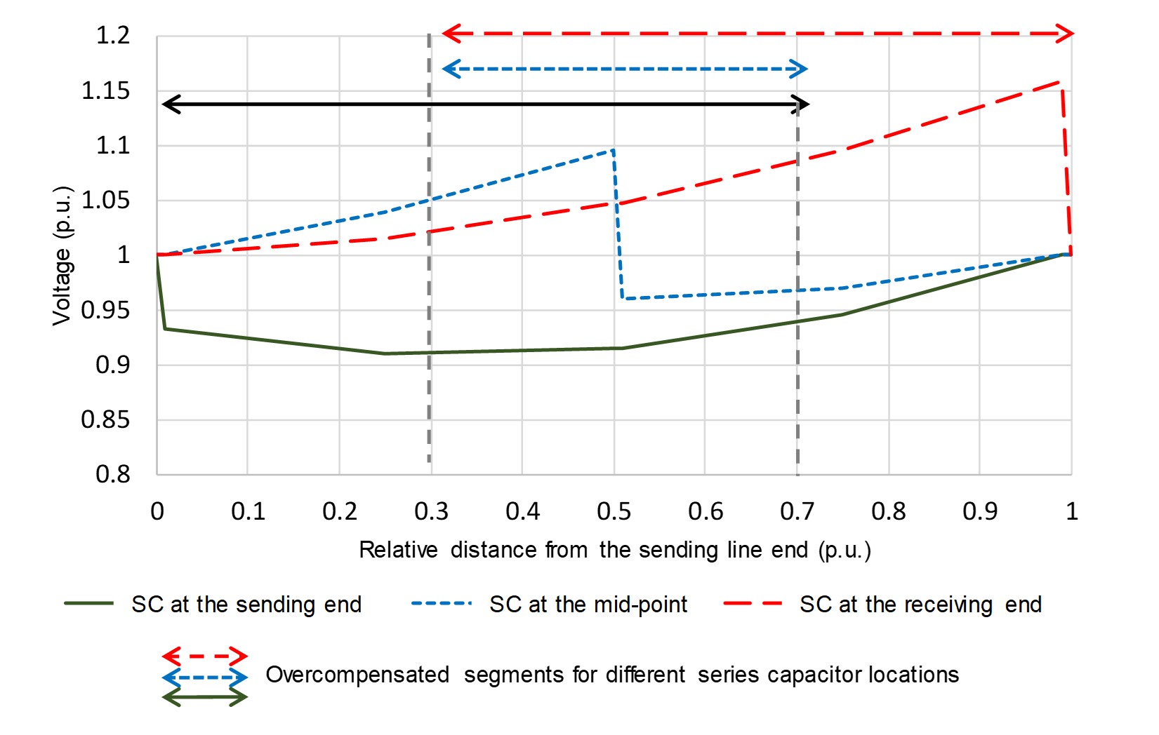
Figure 2 - Voltages along the line and overcompensated line segments for a 70 % compensated transmission line with three different series capacitor (SC) locations. The power flow double surge impedance loading at the receiving line end and both line end voltages are regulated to 1.0 p.u
Some CIGRE TBs have series compensation with normal compensation degrees as a topic. For example, CIGRE TB 693 addressed equipment for series (and shunt) compensation and CIGRE TB 554 focused on the performance evaluation and applications review of existing thyristor control series capacitor devices. CIGRE TB 411 addressed protection, control and monitoring of series compensated networks.
This TB focuses on the impacts of the transmission line overcompensation on the following power system and protection issues, which are well known for normal compensation degrees:
- Steady-state voltage levels and voltage fluctuations that may affect the selection of basic insulation levels;
- Stability and dynamic voltages of the power system with overcompensated lines;
- Abnormal voltages during grid faults including transient overvoltages;
- Transient recovery voltages of circuit breakers;
- Ferroresonance;
- Subsynchronous resonance phenomena; and
- Protection challenges and strategies.
Series compensation, including overcompensation, improves the stability after grid faults, affects fault currents, steady state voltages, dynamic and transient overvoltages, and increases transient recovery voltages in the circuit breaker terminals.
Main findings in this report are:
- At the substations connected to the overcompensated line segment, voltage variations and overvoltage risks increase with the increased capacitance of the series capacitor and the increased compensation degrees.
- Transient overvoltages tend to be higher with overcompensation, with higher capacitance values, longer line lengths, and higher rated capacitance currents. High series capacitance values are associated with high compensation degrees or increasing line lengths with the same compensation degree. Also, higher rated current of the series capacitor leads to higher maximum charging of the capacitor, which creates higher overvoltages. Countermeasures for these exist but are expensive. For example, increasing the compensation degree from 60 % to 140 %, can increase the transient overvoltages from 1.25 p.u. to 2.59 p.u.
- Transient recovery voltages are affected by the same issues as transient overvoltages. The transient recovery voltages and the rate of rise of recovery voltage seem to increase with increasing compensation degrees but countermeasures for these exist.
- Challenges with the voltage control and insulation coordination increase with overcompensation.
- Overcompensation leads to increased risk of resonance issues including a larger risk of fundamental frequency resonance. An overcompensated line connected to the reactances of the background and connection grids may create a situation where, at the connection point, an active voltage control sees a 100-percentage compensated system, which is resonant at the fundamental frequency.
- When planning the grid, 100 % compensation should be avoided. If it is not possible to avoid 100 % compensation, detailed simulation studies should be performed to ensure the proper operation.
- Overcompensation can lead to increased losses if parallel transmission paths have different X/R ratios.
- With overcompensation it becomes more important to use differential protection as the main protection for lines for reasons including a higher risk for current inversion with overcompensation.
The TB did not find any technical issues that would completely prevent overcompensating a line. The findings listed above may require costly mitigation methods for unwanted phenomena or lead to high operational costs (e.g. high losses.) Hence, thorough technical and economic analyses are needed in order to decide if investing in overcompensation is feasible. Overcompensation leads to a more complex power system and therefore it may often be better to avoid overcompensation. Serious study and planning analysis are therefore necessary and the TB provides insight on what to study and how to organize the research.
Voltage and power controls are typically designed for inductive systems. Therefore, the total sum of the reactances of the series compensated system including equivalent source impedances, transformers, line and the series capacitance should be inductive. Overcompensated and normally compensated lines have an overcompensated (capacitive) line segment near the series capacitor. Adding active voltage control in the segment causes voltage increase with the inductive load, a behaviour, which is the opposite compared with the normal case and is explained in the TB. Therefore, the only viable option to control voltages at the overcompensated (or close to 100 % compensated) segment is indirect: by controlling the voltages outside the overcompensated section.
Ferroresonance involving series-compensated lines is most likely to occur in association with unloaded transformers connected radially to the series compensated line.
The inadvertent switching operations of overcompensation may produce natural frequencies in the super-synchronous mode and hence the transient torques and their impact has to be studied to confirm that no superharmonic frequency resonances will occur.
A thorough analysis is required to rule out the subsynchronous controller interaction with overcompensated systems. Several controller interactions cases have been illustrated in the literature.
The protection of overcompensated lines and adjacent lines requires special attention. Voltage and current inversion may occur during some faults along the series or overcompensated line. Overcompensation changes the voltage inversion and seems to increase the line segments where the faults can cause current inversion as simulation results in Figure 3 shows. The system in Figure 2 shows the line segments along the line, where a line fault can cause voltage and current inversion for two compensation degrees. The simulated system had one series compensated line, adjacent lines at both line ends and equivalent grids. The TB presents two methods of calculating of the line segments where faults can cause voltage and current inversion. This helps in protection planning and analysis.
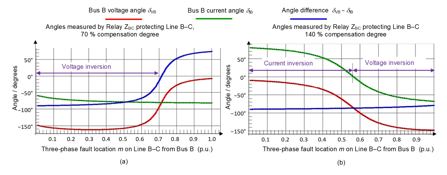
Figure 3 - Voltage and current inversion from the short circuit simulations for a distance relay ZBC protecting a series compensated line B–C for (a) 70 % and (b) 140 % compensation degrees. Current inversion will occur when the green curve (current angle at the relay substation) is positive and voltage inversion occurs when green and blue curves are below zero (both current angle and the subtraction of voltage and current angles at the relay substation are negative)
For overcompensated lines, it is preferred to use differential protection rather than distance protection. Differential relays are not affected by voltage inversion but they can in some cases face problems with current inversion if proper mitigation actions are not used. If distance relays are used, they should be adapted for voltage inversion.
- [1] [1] Harjula, A.; Tuominen, J.; Haarla L.; Holmgren, M. Finnish experience on protection of series compensated network. Paper 307 in CIGRE Study Committee B5 Colloquium, Auckland New Zealand, Sep 11–15, 2017. [2] Haarla, L.; Tuominen, J.; Harjula, A.; Eriksson, H.; Saha, M. M.; Lidström, S. (2016) Testing of the Relay Protection for Overcompensated Lines. In IET International Conference on Developments in Power System protection DPSP 2016, Edinburgh, UK, 7–10 March 2016. DOI: 10.1049/cp.2016.0018

Other Technical Brochures