Vibration Modelling of High Temperature Low Sag conductors – Self-damping characterization
High temperature Low Sag (HTLS) conductors are now installed regularly by some utilities around the world to increase the capacity of existing overhead lines and/or for other considerations. Electrical, thermal as well as mechanical aspects of HTLS conductors have already been covered in CIGRE Technical Brochures 331, 426, 695 and 763. To make sure that they will perform as expected over the long life of the line in which they are installed, the transmission line designers must be able to predict the behaviour of HTLS conductors with respect to aeolian excitation to avoid conductor failure due to fretting fatigue.
Convenor, Author
(IT)
G. DIANA
Secretary
(IT)
G. SANGALLI
P. CHAN (CA), V. CHARI (IN), F. CORDÒ (IT), T. FURTADO (BR), K. HALSAN (NO), J. HAVEL (US), J. HUANG (US), T. KAVANAGH (IE), S. KOLOSOV (RU), S. KRANZ (US), H.J. KRISPIN, Author (DE), M. LANDEIRA, Author (ES), D. LI (CN), B. LIU, Author (CN), I. LOPEZ (ES), A. MANENTI, Author (IT), M. MITO (JP), R. PAUVEL (FR), C. ROZE, Author (FR), E. RUGGERI (US), N. SAHLANI (US), H. SAKAI (JP), W. TROPPAUER (AT), P. VAN DYKE, Author (CA), A. VINOGRADOV (RU), B. WEBB (US)
Corresponding Members: I. BANCHI (IT), D. HAVARD, Author (CA), T. LANDEIRA (ES), A. MOGILEVSKY (CA), J.P. PARADIS (CA), D. PROCTOR (US), D. SUNKLE (US), S.M. UEDA (BR)
Reviewers: SARAH CHAO SUN (AU), RUY CARLOS RAMOS DE MENEZES (BR), ASHRAF EL DAMATTY (CA)
To reach this purpose Working Group B2.58 has been established with the following Scope of Work:
“Modelling of Aeolian vibrations of High-Temperature Low-Sag (HTLS) conductors, including recommendations for laboratory tests on conductors and fittings. The aim is to assist overhead line engineers to improve line protection by being better able to predict the behaviour of overhead lines with respect to aeolian excitation”.
It is worth pointing out that the term “Modelling” in the Scope of Work refers mainly to HTLS conductors self-damping modelling, while modelling of the conductors behaviour with respect to vortex shedding (aeolian vibrations) has been already covered by previous Working Groups and is already the subject of several CIGRE publications and a 2018 Springer Green Book “Modelling of vibrations of overhead lines conductors, Springer, ISBN 978-3-319-72808-7” based on the analytical and experimental studies performed by several researchers in the last decades.
The conductor self-damping is related to the internal damping of tensioned conductors bending induced by transverse vibrations. The bending causes relative movements between the wires or strands of the conductor, movements which are constrained by friction between them. Under conditions common to vibration of overhead line conductors, the friction is great enough to prevent gross sliding. However, there is micro-slip at the edges of the inter-strand contacts, so there is energy dissipation by friction. In addition, the frictional forces cause shear strains at the contacts with resulting material damping. The amounts of dissipation that occur due to these phenomena is called conductor self-damping.
As a first step, the influence of the conductor temperature on the HTLS conductors self-damping has been examined. It can be found in literature that the conductor self-damping generally increases as the conductor temperature increases. This is probably one of the facts – together with the particular structure of some type of HTLS conductor – that leads to claim that HTLS conductors are ‘self-damping’ conductors, meaning that they do not need additional damping, in the form for instance of vibration dampers, to maintain the aeolian vibration level within safe values.
Thus, the main objectives of this brochure were:
- To identify the effect of temperature on HTLS conductor self-damping
- To identify the effect of temperature variations and wind excited vibration cycles on HTLS conductor self-damping
- To identify a procedure to test HTLS conductor self-damping with the aim of using the measured self-damping data to simulate the HTLS conductor behaviour with respect to aeolian vibrations and design an adequate damping system whenever required
- To identify the effect of temperature variations combined with vibration cycles on the behaviour of the different types of clamping systems used for HTLS conductor fittings
Tests were performed in laboratories (see Figure 1) during the preparation of this brochure to evaluate the impact of temperature, thermal cycles and vibration cycles on conductor self-damping, with the following results:
- It was confirmed that the conductor self-damping increases as the conductor temperature increases. This is mainly due to the fact that as the temperature increases, the load on the aluminium external layers decreases. Therefore, the microslips between wires during vibration occur more easily and more energy is dissipated. Nevertheless, it was recommended to evaluate HTLS conductor self-damping at ambient temperature based on the following facts:
- Most TSOs indicated that HTLS conductors generally do not operate at the maximum continuous operating temperature they are designed for;
- It was found and verified through wind-tunnel tests that even at relatively low wind speed (the one responsible for aeolian vibrations) the conductor temperature decreases in a large amount
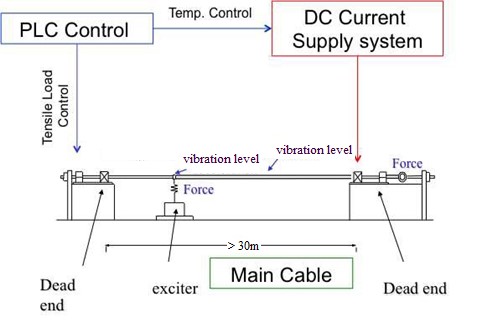
Figure 1 - Test bench layout
Measurements have shown that – mainly at low frequency - self-damping values of HTLS conductors at ambient temperature do not substantially differ from those of standard ACSR conductors (Aluminium Conductor Steel Reinforced), thus requiring a correct investigation about the need of additional damping to safely control the aeolian vibration level – see Figure 2 and Figure 3.
Tests have been also performed on laboratory spans (see Figure 1), subjecting some type of HTLS conductors to thermal and vibration cycling. Thermal cycles were performed between ambient temperature and up to the continuous operating temperature of the HTLS conductor. The vibrations were set to a f ymax level of 90 mm/s and the duration was set at 10 million cycles. Tensile load has been controlled to reproduce the behaviour of a real span (see Figure 1). It was found that:
- HTLS conductors:
- Vibration cycles are mainly responsible for the reduction of conductor self-damping after ageing
- Thermal cycles have a very low impact on conductor self-damping
- Standard ACSR conductors:
- Show also a reduction of self-damping after vibration cycle ageing
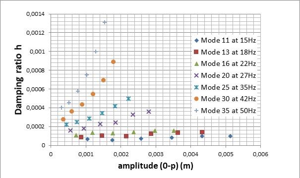
Figure 2 - ACSR “Condor” self-damping at 20% RTS - ambient temperature, before ageing
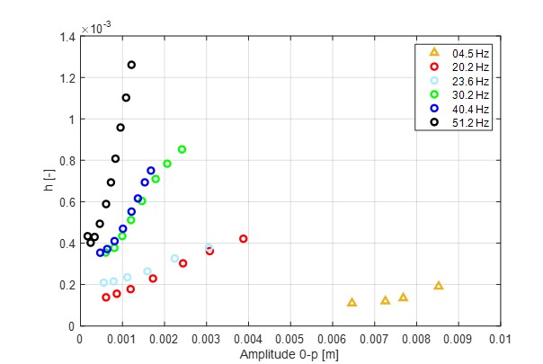
Figure 3 - ZTACIR conductor at 25% RTS - ambient temperature, before ageing
Where ACSR means Aluminium Conductor Steel Reinforced, ZTACIR means ultra thermal resistant aluminium alloy conductor, invar steel reinforced and RTS is Rated Tensile Strength of the conductor.
Since HTLS conductors – due to wind effect or when not operated at the maximum continuous temperature - have a similar behaviour, mainly at low frequency, than standard ACSR conductors regarding self-damping reduction after vibration ageing, it was recommended to evaluate the HTLS conductor aeolian vibration behaviour using the self-damping data at ambient temperature, before ageing, as it is done for ACSR conductors.
Simulations of the aeolian vibration behaviour of HTLS conductors with and without dampers have been performed using the measured self-damping data – see Figure 4 and Figure 5. The results of the simulations clearly show that mainly at low frequency, below 20 ÷ 30 Hz, as a function of the conductor type, dampers are needed to control the aeolian vibration level below the generally considered limit of 100 ÷150 microstrains.
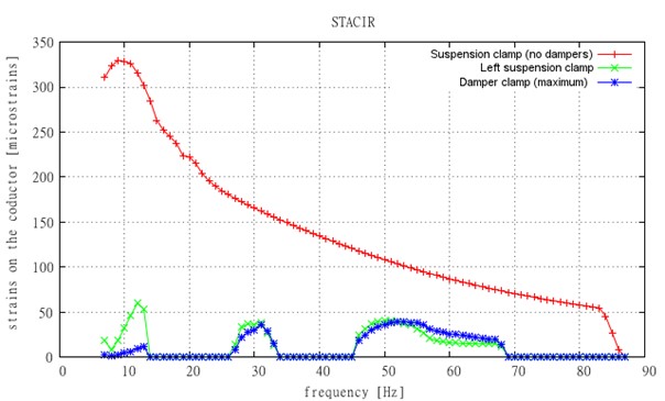
Undamped conductor (red line). Aeolian vibrations with damper (green and blue lines)
Figure 4 - ZTACIR conductor at ambient temperature, 25% RTS, before ageing: Aeolian vibration level – strains at the suspension clamp
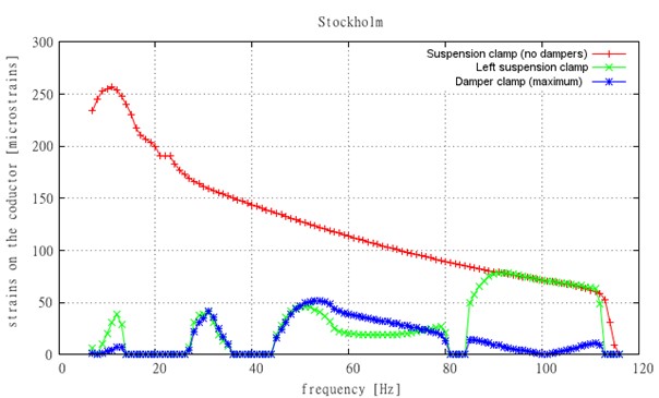
Undamped conductor (red line). Aeolian vibrations with damper (green and blue lines)
Figure 5 - Type 4 Stockholm conductor at ambient temperature, 20% RTS, before ageing: Aeolian vibration level – strains at the suspension clamp
Where the Type 4 conductor is an annealed aluminium conductor, polymer matrix composite core supported.
Tests have been performed to evaluate the performance of the clamping system of the fittings used for HTLS conductors, mainly in relation to the clamp loosening effect. The impact of thermal cycling and large amplitudes of vibration on the clamp performance has been evaluated using the same procedure studied for conductor self-damping testing (see Figure 1).
The tests have been performed with three types of clamping system (see Figure 6):
- Metal to metal bolted clamps (directly on the conductor or on armour rods);
- Clamps with rubber cushions, generally identified as nutcracker clamps;
- Clamps attached to the conductor with helical rods.
Temperature measurements on some part of the different evaluated clamps have been also performed (see Figure 7).
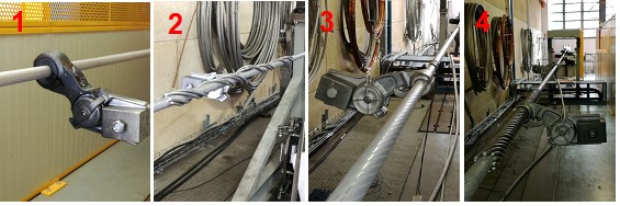
Figure 6 - Tested clamping systems (tests with Type 4 Stockholm conductor)
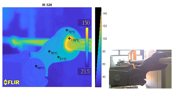
Figure 7 - Temperature distribution – nutcracker clamp (tests with Type 4 Stockholm conductor)
Conclusions
As a conclusion of the extensive testing performed and discussion among the members, it has been agreed that:
- HTLS conductor self-damping should be measured on a new conductor sample at ambient temperature with the standard procedure as described for instance in IEC 62567 or IEEE Std 563 for standard conductors, leaving as an option the measurement of the conductor self-damping after temperature and vibration cycles performed as described in the proposed procedure.
- It was found that, mainly at low frequency, self-damping values of HTLS conductors at ambient temperature does not substantially differ from those of standard ACSR conductors, thus requiring a correct investigation about the need of additional damping to safely control the aeolian vibration level and, therefore, de-claiming that HTLS conductors are self-damping conductors.
- Metal to metal bolted clamps and clamps attached to HTLS conductors with helical rods do not seem to be sensitive to thermal and vibration cycling when properly designed.
- The rubber type choice is of paramount importance for rubber cushioned clamps: the rubber type has to be carefully selected in view of application on high temperature conductors.

Other Technical Brochures