DC-DC Converters in HVDC Grids and for Connections to HVDC systems
The CIGRE Technical Brochure was developed by the Working Group B4.76 which was established in 2017. The main objectives of the WG were to (i) evaluate feasibility of DC-DC converters for applications within DC transmission grids, (ii) understand applications, role, need, basic technical properties and (iii) evaluate applications of interconnecting HV and MV DC systems including DC tapping.
Convenor
(UK)
D. JOVCIC
Secretary
(CA)
G. KISH
A. DARBANDI (CA), J. ROBINSON (DE), R. FERRER (ES), X. GUILLAUD (FR), A. JUNYENT-FERRE (GB), A. NAMI (SE), T. MERIDJI (CA), D. WOODFORD (CA), O. GOMIS (ES), P. DWORAKOWSKI (FR), A. JAMSHIDIFAR (GB), M. BONGIORNO (SE), M. SAEEDIFARD (US)
Corresponding members: R. AZAR (CA), W. LIN (CN), J. PAEZ (FR), S. ELIMBAN (CA), C. ZHAN (CN)
Introduction
As of now, no DC-DC converter for DC transmission grid applications has been installed or built, although many technical studies have been published by researchers including manufacturers.
DC-DC converters have been mentioned in several recent CIGRE technical brochures related to DC grids and are expected to be one of the main components in future DC grids, beside AC-DC converters and DC Circuit Breakers.
The DC-DC converter is visualised as a transformer in traditional AC grids, but is substantially a more complex device and can take many additional functions, like a circuit breaker and a power flow controller.
Some of the important motivations for installing DC-DC converters include:
- Interconnecting DC systems of different voltages,
- Interconnecting DC systems having different topologies,
- Resolving grounding challenges in large DC grids,
- Interconnecting DC systems of different vendors and avoiding interoperability challenges,
- Interconnecting line commutated HVDC with voltage source systems,
- Tapping on HVDC lines or connecting with MVDC (Medium Voltage DC) systems,
- Control of power flow in DC lines and DC grids,
- Voltage drop compensation,
- Fault current interruption and fault current limiting,
- Firewall separation of DC grid segments,
- Multifunctional device strategically located in DC grids.
Presently, the largest installed DC-DC converters in industry are of the size of around 1 MW which are used in vehicle propulsion.
Design and modelling of DC-DC converters
Because of generally low TRL (Technical Readiness Level) of DC-DC converters, it was decided that this WG would produce models on PSCAD platform for two representative topologies and test cases in order to best support and harmonize future studies, and to simplify transfer of the knowledge from this WG. The same two test case models were used throughout the brochure to illustrate by the way of simulation all the key conclusions in various chapters. Users should be able to replicate all the responses from the brochure using provided PSCAD model files, except studies in Chapter 7. These models are available on e-cigre for CIGRE members. The real time models on RTDS platform were also produced.
Two test models are developed in such a way not to be linked with any manufacturer but to represent two distinct families of DC-DC converters:
- Isolated DC-DC converter, also called the DAB (dual active bridge) DC-DC converter, rated 600 MW, ±400 kV/±200 kV, 150 Hz as shown in Figure 1, and key parameters listed in Table 1. This topology facilitates higher voltage stepping ratios and galvanic isolation and inherent DC fault blocking.
- Non-Isolated DC-DC converter, rated 600 MW, 400 kV/398 kV, 150 Hz, as shown in Figure 2, with key parameters listed in Table‑2. This topology is less costly, and losses are expected to be lower, but voltage stepping ratio should be low. DC fault blocking can be realized by using appropriate type of switching cells.

Figure 1 – Isolated bidirectional DC-DC converter

Table 1 - Design parameters for 600 MW, ±400 kV/±200 kV, isolated test DC-DC converter
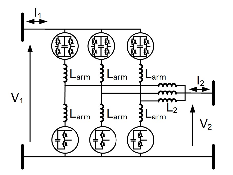
Figure 2 – Non-Isolated bidirectional DC-DC converter

Table 2 - Design parameters for 600 MW, 400 kV/398 kV non-isolated test DC-DC converter
The test DC-DC converters employ the MMC (Modular Multilevel Converter) technology as the state-of-the-art building block for VSC applications. MMC with HB (Half Bridge) topology is used in the lower arms while MMC with FB (Full Bridge) topology is used in the upper arms in the non-isolated DC-DC. HB MMC is employed in the isolated DC-DC converter, although this converter could also employ MMC with FB topology. The voltage ratings are chosen to fit in the two DC-DC converter placeholders in the CIGRE B4.72 DC grid test system. A consensus has been reached among WG members, on the representative technologies and basic properties of these two test cases, although technologies have been selected to be vendor-neutral. The discussions within the WG and the results of technology survey of manufacturers, concluded that DC-DC converters are technically feasible for HVDC grid applications.
A summary design process for each of the two test converters is presented in Chapter 3 of the brochure. The key trade-offs for most important converter parameters are discussed based on typical performance specification, and simulation results illustrate satisfactory performance of the test cases.
The modeling of each test DC-DC converter is described in generic, platform-neutral way. The underlying average value models for key components (e.g. valves) are taken from previous CIGRE work in B4.57, and then expanded for the intended use. Specifically, the blocked converter responses, which are important for simulating faults and start-ups, are represented accurately with the proposed models.
The test models include full DC-DC control systems and control schematics; these are briefly discussed in the brochure.
DC-DC functions in DC grid under normal operation
Numerous HVDC links operate worldwide, each with an optimised DC voltage, and their integration in future DC grids will require DC-DC converters.
There are several HVDC topologies, two different technologies (line commutated and voltage source) and multiple manufacturers. In general DC-DC conversion would provide one possible solution for interconnecting these systems, and it could further help with some interoperability issues.
Numerous grounding options have been used with HVDC systems, and the regulations for ground current flow are becoming more stringent. The isolated DC-DC topology would facilitate power exchange between two DC systems of different ground strategies.
As DC grids increase in size, there might be a need for multiple DC-DC converters in proximity. In such cases, a DC hub would be an effective solution, as illustrated in Figure 3. DC hub is an extension of DC-DC converter concept, and can be described as an electronic DC substation, interconnecting multiple DC lines of different DC voltages and providing a range of other functions like DC fault isolation and power flow control.
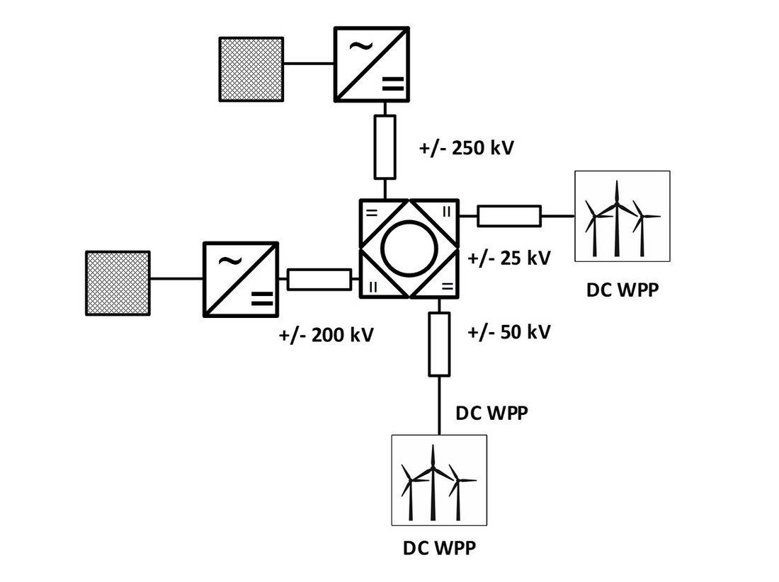
Figure 3 – 4-port DC hub for interconnecting 2 HVDC systems and 2 wind farms
DC-DC converter in DC grid under DC fault conditions
DC-DC converter will have inherent DC fault blocking capability and will not require external DC circuit breakers. DC-DC converter will therefore be able to operate as a DC circuit breaker, and can be integrated in DC grid protection, although the responses will not be the same as DC circuit breaker responses. Some DC-DC converters will be blocked, while others will be able to operate in fault-ride-through and to provide continuous current control under DC faults.
Figure 4 shows the simulation results of the non-isolated DC-DC converter test system from Figure 2 for a 200 ms worst case DC fault at the HV terminals (V1 side), which indicates that the fault is not transferred to the LV side and that internal variables are well-controlled (DC-DC is blocked).
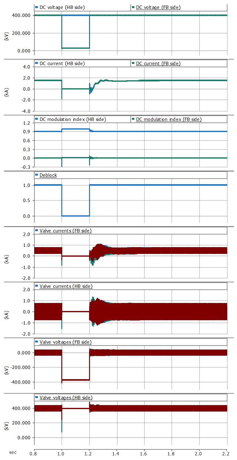
Figure 4 – Non-isolated DC-DC converter response for a 200 ms fault on HV side
Control of DC-DC Converter in DC grids
In general, DC-DC converter facilitates control of one external system variable. The control variable will be selected by the DC grid designer or operator/dispatcher, and could be power flow, DC voltage on either side, impedance, or some combination of basic variables.
DC-DC converter will be able to provide a range of other control functions in DC grids, like grid stabilisation, black start or firewall separation between DC grid segments.
DC-DC Converters for connecting HVDC to MVDC
MVDC systems have been studied separately in SC B4, and their connection with HVDC grids and tapping on HVDC with MVDC output will generally require DC-DC converters with higher stepping ratios and lower power ratings. The converter topologies described in previous chapters may not be suitable. Some typical applications include connections with MVDC wind farm or other renewable energy collection grids.
Chapter 7 describes new HVDC-MVDC DC-DC topologies and presents simulation responses, using two test cases: 1) for HVDC to MVDC grids interconnect: 320 kV/50 kV, 100 MW (and also ±320/±50 kV, 200 MW) DC-DC converter, and 2) for HVDC tapping to establish a MVDC output bus: ±320 kV/±20 kV, 55 MW DC-DC converter.
Figure 5 shows the non-Isolated MMC autotransformer which is studied as one of the topologies for connecting with MVDC systems.
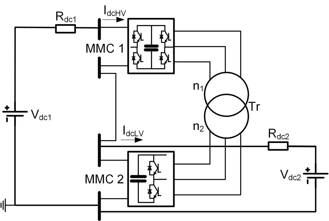
Figure 5 – Non-Isolated MMC Autotransformer
Conclusion
The brochure provides guidance on functionalities, performance, and modelling of DC-DC converters for the application in DC transmission grids. Two, 600 MW DC-DC converter test systems (an isolated and a non-isolated topology) are described and complete PSCAD models are made available, which will be of help to future DC grid developers. The brochure describes motivations for introducing DC-DC converters, design, modelling, their functionalities in normal operation, under DC fault conditions, and control options.
The last chapter presents DC-DC converters for connecting with MVDC systems and for tapping on HVDC lines. The appendices include list of symbols used, description of PSCAD models, description of RTDS models, and a survey of five DC-DC converter manufacturers.

