Design guideline for substations connecting battery energy storage solutions (BESS)
Renewable energy technologies are being introduced to generate large amounts of electricity for reducing carbon emission. The impact of the increasing number of renewable energy power plants may cause the power grid to face an effect or change the flow pattern of power systems, for example, the reverse power, power variation, etc. Therefore, the Battery Energy Storage System (BESS) has begun to be introduced widely as a part of solutions.
Members
Convenor
(TH)
S. PRUNGKHWUNMUANG
Secretary
(CN)
Y. DING
T. TAMAKOSHI (JP), S. PANIGRAHI (US), K. KAWAKITA (JP), M. OSBORNE (GB), M. FICARRA (IT), K. ALMUTAIRI (SA), H. WOLFSCHMIDT (DE), B. LEI (CN), C. COSTAN (AU), K. DHANAVARAVIBUL (TH)
Corresponding Members: M. TIWARI (IN), Z. XIANWEN (CN), L. BUONO (IT), B. LI (CN), M. BA-AZZIM (SA), T. FREY (CH), Y. SHI (CN), N. CHATRUNG (TH), W. APHICHATO (TH)
Introduction
The battery storage system has advantages over other energy storage technologies in that it has wide variety of options which provide high energy density, high efficiency, fast response, modularity, less geographical limitation, small footprint, low maintenance, ease of erection and installation. The size of battery can be implemented into a wide range of systems from some kWh for household use up to GWh for the grid system.
Although other energy storage technologies are well established, BESS is considered as a new evolving technology which many utilities and system owners may not be familiar with. This Technical Brochure will provide a guide to how to implement BESS in a substation, both for existing and new substation projects.
Technical Requirement for a BESS-Connected Substation
Integrating the BESS-connected substation to the power grid, it is necessary to understand the Grid codes. Although such requirements may vary in each country, the main requirements such as fault ride through, harmonic compliance, ramp rate regulation and frequency regulation are share a common principle.
BESS in good network configuration leads to cost-optimisation and reliability. The local grid configuration will need to be reviewed and, adjustments may be required. As it becomes more viable to install RE, microgrids operating at low or medium voltage are becoming more common place. These systems significantly benefit from utilising BESS together with power generation, electrical loads, information and communication technology systems. An example of a microgrid with BESS operating is shown in Figure 1.
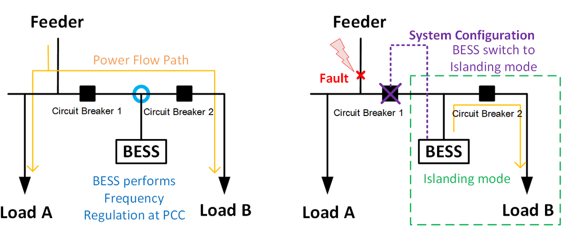
Figure 1 - Samples of operating scenarios
During normal operation, microgrids connect to the main grid by feeders and BESS performs frequency regulation. When there is an unexpected fault or outage on the feeder connected to the microgrid, the microgrid has to switch to island operation mode.
For BESS-connected new substations, the equipment ratings and control and protection system can be designed to support the BESS rating and functions. However, for an existing substation, the legacy ratings should be verified so that they can support the additional loading due to the BESS. In addition, the existing control and protection system should be reviewed as well, especially the communication protocol between existing equipment, metering and the substation control system and SCADA. The auxiliary service requirement for BESS is quite onerous and must be considered in the design, whether as an internal or external auxiliary supply according to the required function of the BESS.
The grounding system configurations will have different characteristics depening on the selection of the grounding configuration and the neutral grounding system.
The environmental impacts from BESS will be concerned and mitigated, for example, noise pollution, visual impact, chemical pollution, etc.
Safety is paramount; however, installing BESS in to substation will add the risk of fire and even explosion. Hence, additional safety measures will be required, especially for grid-scale BESS.
Substation Design
Battery installations can be installed either indoors or outdoors depending on environmental factors such as flooded areas, ambient temperature, pollution levels, seismic areas, snowy areas, etc. Moreover, the installation of BESS within a building is appropriate in the community area. Installing BESS indoors can also reduce both visual impact and noise pollution.
Regarding National Fire Protection Association (NFPA) standards, these two types of installation have different separation distance requirements to facilitate firefighting and the spread of fire. In additional, each battery type has different factors to consider regarding fire spread, and suitable fire-suppression systems.
An indoor installation covers a dedicated-use building which is intended for the installation of a BESS only, and a non-dedicated-use building which can be an occupied work centre. The former is located more than 100 ft. (30.5 m) from any other buildings or equipment, the separation distance requirements can be omitted. The latter is required to have minimum of 3 ft (914 mm) from the wall in the storage room or area.
An outdoor installation covers BESS located in remote area and near expose installation. A BESS is installed outdoors remotely more than 100 ft (30.5 m) from any other buildings or equipment, separation distance requirements can be omitted. However, a minimum of 10 ft. (3 m) separation distance from any other buildings or equipment is required. The separation distances requirements from such installations can be reduced to 3 ft. (914 m.) if the enclosure has a 2-hour fire resistance rating
The output-input power and energy of the BESS at the PCC can be estimated by a component rating process. The overall rating and efficiency of the main components including transformer part, PCS (or inverter) part, current-carrying component (copper loss), battery are as shown in Figure 2.
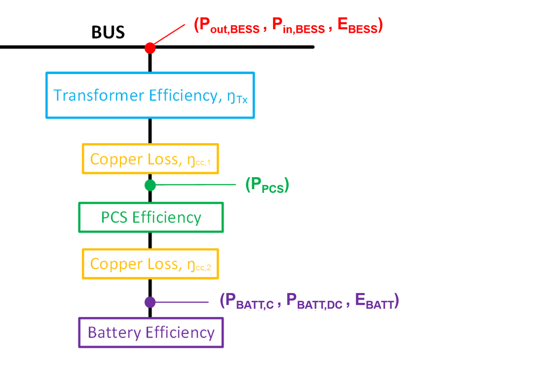
Figure 2 - The Draft Single Line Diagram
Installation and Commissioning
There are many battery technologies for BESS, each with different characteristic, some are requried special equipment and procedures which will depend on battery technology and the manufacturer’s design. The size and weight of battery modules is also significant (difference in battery technologies) and affects the transport logistics.
An example of NaS battery manufacturer, the container solution allows it to be 95 % assembled and tested in the factory for the battery part alone, hence there are minimal steps required for the completion of battery system on site. However, a single container could weight around 25 tonnes and will require heavy lifting machinery to install the modules and to prepare the necessary space for the operation of this machinery during installation and maintenance.
For a lithium-ion battery, the installation method differs between the manufacturers. As an example, the battery can be shipped as separate sets of wholly populated racks while their containers will have some subsystems pre-installed at the factory and then be shipped to site where the battery racks and other subsystem are generally assembled with the container to complete the installation. The battery module can heavy be up to 60 kg making the weight of the whole rack more than a tonne, therefore, special tools may be necessary to move these racks to the installation point inside the container. The replacement of a battery module will also require special tools and procedures.
During the installation and commissioning, for a lithium-ion battery, there is possibility of the battery module being damaged internally during installation and subsequently is a cause of fire, even if there is no external visible damage. If a module is dropped or heavily impacted during installation that module should not be further installed. The installation of a BESS is recommended to be under the supervision of the battery manufacturer.
Regarding guidance from the manufacturer on testing and standard requirements, BESS testing begins from the factory acceptance testing (FAT) for the power conversion system (PCS), Battery System and monitoring system and the control system then continues with the site acceptance sub-system testing, offline and on-line testing, first energisation testing and performance guarantee testing to ensure that BESS can operate efficiently and safely.
After completing the installation of a BESS, a first energisation is required to resolve uncharged and non-equalised elements in the BESS. Following the equalisation of the BESS elements, the series of commissioning tests shall be performed to demonstrate that the BESS functionality and capabilities meet the performance requirements in the technical specifications. The tests can be roughly divided into three groups: parameter tests, performance tests and system implementation tests.
- The parameter test is a mandatory test for every BESS system. This test is required to measure and to evaluate the basic characteristic and performance of the BESS.
- The performance test is required to measure and to evaluate the performance of the BESS to provide grid service for each application classification.
- The system implementation test is required to verify the system conformity.
Maintenance
For a new technology, BESS, development and training of the substation staff may be required, so some elements can be properly serviced by the trained local maintenance team at the substation. The modular design of BESS results in the maintenance being mostly replacement of these modules with their spares according to the scheduled recommendations from the manufacturer. Due to the rapidly changing technology, it is recommended that some key spare parts be stored at site. There may be instances where some major maintenance operation may require special tools and procedures.
Conclusion
Guidance and recommendations provided in this Technical Brochure is useful when consider designing, installing, commissioning and the subsequent asset managing necessary to reliably operate BESS technology. To safely integrate reliable BESS into the power system, the manufacturing and testing standards are regularly reviewed to ensure that the learning and stakeholder experience and risks can be efficiently managed.

Other Technical Brochures