Service Continuity Guide for HV GIS above 52 kV
The Working Group B3.51 successfully filled the gaps on the definition of service continuity during maintenance, repair, extension or on-site dielectric test for High Voltage GIS equipment above 52 kV.
Members
Convenor
(DE)
M. KUSCHEL
Secretary
(CH)
J. HETTLER
S. PACHLATKO (CH), A. FICHEUX (FR), L.V. BADICU (DE), D. VAN HOUWELINGEN (NL), B. GODEAU (BE), M. RECKER (DE), J. KJONAS (NO), A. RICONDO REBOLLO (ES), M.A. MONTOYA ARANGO (ES), I. TING (NZ), A. CANHOTO (PT), A. OBCZYK (PL), B. LINEHAN (IE), C. FARRELL (IE)
In accordance with the terms of reference the Working Group has achieved the following results:
- Definition of the service continuity levels through the so called MRE Code (Maintenance, Repair, Extension), which specifies the number of feeders and busbar sections out of service during MRE activities (incl. on-site dielectric test)
- Provision of a service continuity guide including most relevant aspects, as e.g.:
- Selection and definition of MRE Codes
- Definition of users and manufacturers responsibilities
- Description of the most important technical aspects including safety issues
- Description of the technical background of all relevant aspects
- Elaboration of recommendations for user and manufacturers
- Support of revision of IEC 62271-203 Annex F
With the service continuity guide and MRE Code, users and manufacturers can exchange information more effectively. The users are provided with a tool that enables more planning reliability for service assignments. This Electra contribution summarises the main points in regards of service continuity and gives information, where more details can be found in the Technical Brochure.
Introduction
Gas Insulated Switchgear (GIS) has become a convenient solution (especially in urban and offshore areas) when choosing a new transmission / distribution substation or replacing an old one. This is due to the obvious benefits GIS offers, such as its compactness, low maintenance, safety and reduced visual impact.
However, Maintenance, Repair and Extension of a compact GIS installations in a confined space can be challenging due to restrictions applied e.g., when working on pressurised vessels and partitions at an energised GIS. Often there is no complete awareness of how a failure of a gas compartment could significantly impact the service continuity. Moreover, a clear definition of service continuity for HV GIS (>52 kV) during MRE was missing which would help users and manufacturers exchange information more effectively.
Therefore, in parallel to the IEC maintenance team MT16 of IEC 62271-203, a CIGRE Working Group was established to prepare a new proposal of the informative Annex F of IEC standard 62271-203 in order to support its revision. The revision includes the newly defined MRE Code. The CIGRE Technical Brochure presents the details and background of the MRE Code and provides a guide on how the MRE Code can be used.
MRE Code Definition
To describe and define the service continuity of a GIS during maintenance (M), repair (R), extension (E) or on-site dielectric testing a so called MRE Code was introduced into the IEC. If this is a topic and requested the user and manufacturer shall agree on certain MRE Codes during the quotation phase of a new GIS project. The MRE Code shall be defined for the whole switchgear or specific to a certain GIS section. In most cases the MRE Code will be different for maintenance, repair, extension and on-site dielectric test.
Generally, substations usually consist of three different parts relevant for the MRE definition, shown in figure 1. A feeder bay connects a feeder to a busbar section or another feeder (e.g. ring configurations). A feeder bay consists of a set of interconnected circuit elements. Circuit elements can be: circuit breaker, disconnector, earthing switches, current transformer, voltage transformer, surge arrester and connecting elements. A busbar section is the common connection of several feeder bays. A busbar can be sectionalised in several busbar sections. A busbar without sectionalising is one busbar section. A busbar sectionaliser is the common connection of two busbar sections. The busbar sectionaliser is not considered as a feeder, a feeder bay or a busbar section. A feeder is a connection from a substation to another substation, a transformer, a generator, a reactor, a capacity bank, etc. A feeder is in service when it can be used for power transmission respecting aspects of secure system operation. A feeder is out of service when it cannot be used for power transmission, or aspects for secure system operation are not fulfilled.
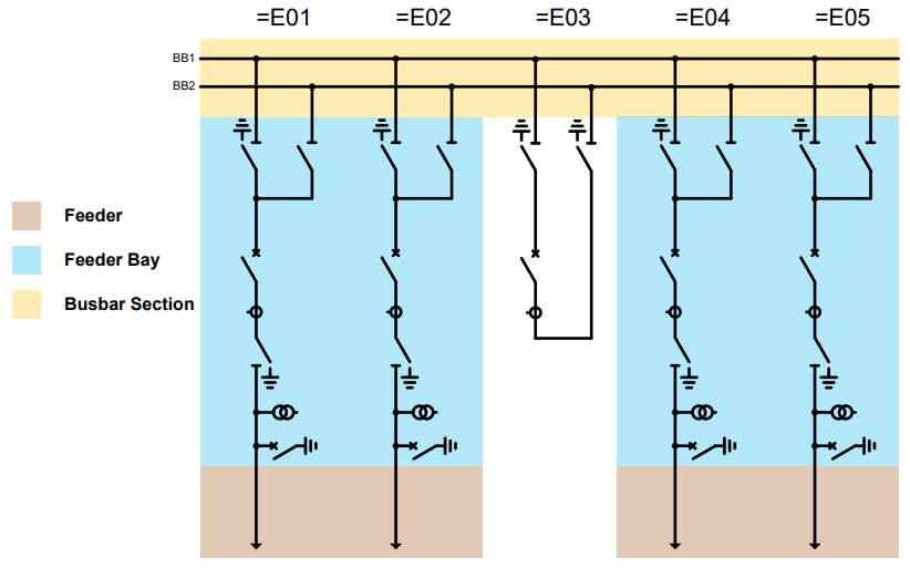
Figure 1 - Exemplary representation of single-line diagram into feeder, feeder bay and busbar section
The MRE Code consists of the three code letters MRE, which represent Maintenance, Repair and Extension. According to IEC 62271-203 chapter F.4.1, the code letters are followed by two numerals, which define the impact of an out of service condition on the service continuity of the GIS. The first numeral defines the number of busbar sections and the second numeral the number of feeders of the related busbar section, which are out of service during maintenance, repair, extension or on-site dielectric test of a GIS. E.g. MRE12 (refer examples figure 3) means one busbar section and two feeders out of service during MRE. Instead of numerals the letter X can be used to describe that all busbar sections and / or all feeders of the related busbar section are out of service (de-energised). Busbar sectionaliser, transfer busbar and feeder bay are not considered and are not relevant for the MRE Code. The brochure contains also other use cases to give a detailed insight into how to use the MRE Code.
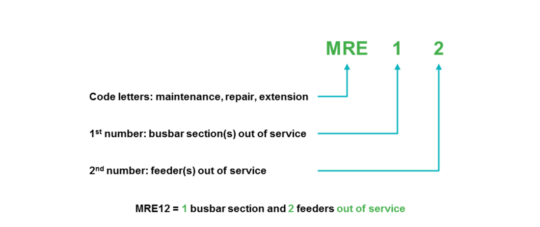
Figure 2 - MRE Code definition for HV GIS above 52 kV according to IEC 62271-203 - Annex F

Figure 3 - MRE12 use case examples: Repair of a busbar disconnector
Technical aspects and recommendations
Beside the description of technical challenges there are recommendations described reflecting the users’ and manufacturers’ experience regarding service continuity. E.g. service continuity come a long with the layout. Good practices in the layout of a substation seek to provide enough space for maintenance activities to minimize the number of elements out of service. For AIS, the above is a practice that most users are very familiar with, and no major discussion arises around it. However, when talking about GIS substations, this becomes a task that needs a deeper analysis because of the interdependency of the GIS elements. There are several options to improve the service continuity capability of a switchgear e.g., by considering:
- Position of important feeder (e.g., distribute critical feeder to separate busbar sections, left and right from the busbar sectionaliser respectively)
- Position of disconnectors and earthing switches
- Busbar separation (e.g., busbar sectionalisers)
- Additional isolating points (e.g., disconnectors)
- Additional earthing switches (e.g., earthing switch at both ends of the busbar)
A fundamental improvement could be the consideration of one or more busbar separations which could be opened in case of a failure. There are different options in this particular case, for example by adding a fully operational busbar sectionaliser switch to the busbar if available. But also, less operational solutions could help to improve the service continuity capability, e.g., additional removable links, although this may require the opening of additional gas compartments leading to a lower level of service continuity (refer to table 1).
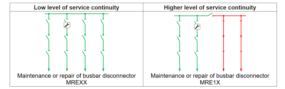
Table 1 - Additional disconnecting elements may increase level of service continuity
But it is also obvious that the approach of adding additional elements to the switchgear is limited and cannot cover all possible failure cases. In this regard it is important to find a well-balanced solution considering the failure rate of the equipment (refer also to CIGRE TB 513) and the costs for the additional measures. When specifying the service continuity requirements, it should be considered, that the complexity of the technical solution will equally increase with the service continuity requirements. In this context low service continuity requirements will lead to easy standardised technical solutions. On the other hand, high service requirements might lead to complex customised technical solutions with the respective impact on costs but enables higher operation flexibility in case of MRE events, figure 4.
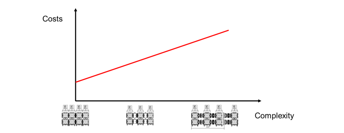
Figure 4 - Schematic complexity-cost diagram
CIGRE TB 585 outlines a decision-making process when designing a substation configuration which considers several factors. This includes the associated single-line diagram which will ultimately define how well the substation will perform when subjected to maintenance, repair, extension and testing activities.
One of the challenges is also the working in gas compartment. Here personnel safety rules during MRE activities shall be strictly observed and given the highest priority. Therefore, the manufacturer should provide the user with a GIS product related design risk assessment and recommended procedures. Highest attention is required if work at pressurised partition is needed. The manufacturer should outline the controls required to allow recommended and authorised work to proceed. Generally, in case such recommendations are missing, any kind of work on pressurised gas partitions while an additional mechanical load or force is applied or can possibly or accidentally be applied are not recommended unless specific countermeasures are considered. Such measures should be defined after a case-by-case risk assessment. Some examples are shown in table 2. There are various approaches to prevent situations which lead to the above not recommended or forbidden works e.g.
- Additional busbar sections
- Additional gas buffer compartments
- Additional intermediate support insulators
- Additional disconnectors/ isolating links
- Appropriate physical arrangement of components
- Specific safety measures (e.g., protective covers or special tools)
A detailed description and more examples and recommendations are given in the brochure. In particular, the following aspects are handled in detail:
- Temporary earthing and short-circuiting
- Site restrictions
- On-site HV testing at switchgear in service
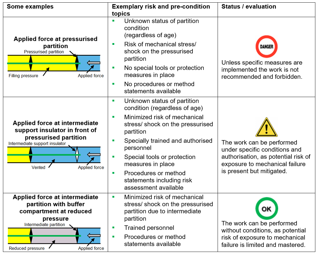
Table 2 - Examples of work evaluation adjacent to pressurised partitions
Finally, in chapter 3 of the brochure the service continuity documentation is in detailed described.
E.g., how to specify service continuity requirements (SCR). The MRE Code can be used in different options, either as a common definition for the whole switchgear or a detailed definition on a feeder and busbar section-based approach. In general, it is recommended to work with common definitions in order not to complicate the topic too much as shown in table 3. If one or more feeders are considered of critical importance by the user, a feeder-based approach could be used for defining the SCR, details see brochure. Further important aspects and recommendation detailed in chapter 3.5 of the brochure are:
- Colour code for service continuity concepts and method statements
- Service continuity concept (SCC) and how to verify it
- Method statement for intervention works on GIS
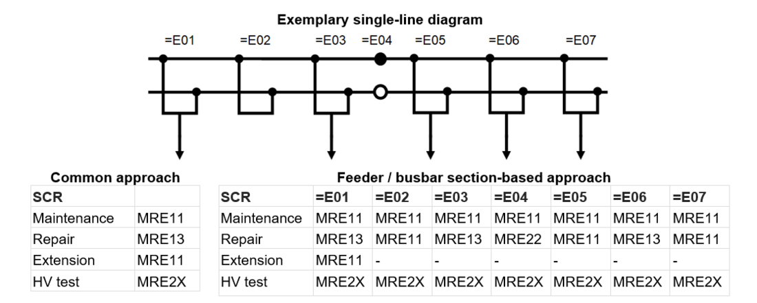
Table 3 - Exemplary specification of service continuity requirements
Processes and responsibilities
Recommendations to support the exchange of information regarding service continuity between the users and the manufacturers are provided in chapter 4 of the brochure. In particular, it provides a guideline on how and when, during the life cycle of a GIS, the service continuity understanding of the HV GIS should be defined, discussed and agreed between user and manufacturer.
Various annexes in the brochure provide further valuable information for users and manufacturers:
- Appendix A: Definitions, Abbreviations and Symbols
- Appendix B: Links and References
- Appendix C: User and manufacturers survey results dedicated to service continuity
Conclusion
- Working Group B3.51 successfully filled the gap and provide a systematic approach for the service continuity topic for HV GIS above 52 kV;
- To handle the complexity of service continuity a so called MRE Code was introduced specific to busbar sections and feeders of the GIS on out of service condition during maintenance, repair, extension or on-site dielectric test;
- This CIGRE Technical Brochure is designed as an application guide for users and manufacturers and contains besides the definition of service continuity, all relevant aspects and technical background related to it;
- With this Technical Brochure and the introduced MRE Code, users and manufacturers can exchange information more effectively. Finally, the users are provided with a tool that provides more planning reliability for service assignments;
- With revised Annex F of IEC 62271-203 and this technical brochure the basis is laid to collect experiences with the MRE Code system;
- Moreover, with the application of the MRE Code the requirements of the users can be more easily and systematically analysed by the manufacturers. At the end this will lead to improvements of design and engineering.

Other Technical Brochures