Design, test and application of HVDC circuit breaker
HVDC transmission is used for bulk power transmission over long distances, to interconnect asynchronous AC networks or for underground/submarine cable transmission with lengths above several tens of kilometres, e.g. in case of offshore wind power plant connections to the mainland.
In contrast to LCC-HVDC systems, systems based on Voltage Source Converter (VSC) technology assume an increasing role in worldwide grid developments to allow a more flexible operation and to be able to connect weak AC grids, such as networks dominated by renewable generation infeed. The VSC-HVDC technology enables the use of multi-terminal DC systems including meshed DC grids with multitude of converter stations and DC transmission lines.
Members
Convenor
(CN)
J.Z. CAO
Secretary
(CN)
J.C. WANG
KMS Manager
(AU)
R. HUGHES
P. TUENNERHOFF (DE), L. RECKSIEDLER (CA), J. DORN (DE), C. GAO (CN), M. WANG (BE), M. ABEDRABBO (BE), R. SMEETS (NL), T. INAGAKI (JP), H. ITO (JP), Y.F. YANG (CN), W. GRIESHABER (FR), D. JOVCIC (UK), J. LILJEKVIST (SE), T. SOMMERER (USA), Á. HERRANZ (ES), W. LI (CA), R. GU (CN), T.H. CHENG (CN), T. ISHIGURO (JP), K.P. ZHA (CN), T. MODEER (SE), T. AN (CN), X. LI (CN), H. GUO (CN), S. AZAD (CA), T. KARMOKAR (DE), R. ZENG (CN), X. ZHAN (CN), Z.R. ZHANG (CN), Y.S. CHEN (CN), Y.H. SHAN (CN), W. LIU (CN), W.D. ZHOU (CN), J.L. ZHANG (CN), X. JING (CN)
To be able to reliably operate such DC networks with multi-gigawatt transmission capacities, HVDC circuit breakers (HVDC CBs) have been identified as a key component to make and break DC currents during normal grid operation as well as to quickly isolate faulted segments of a DC transmission grid minimising the impacts on healthy system parts and thus avoiding large-scale system outages.
Several HVDC CB concepts have been developed in recent decades. However, to-date, only ACI and MPE HVDC CBs have been commissioned in HVDC applications, and several operational experiences have been reported. These two CB types have also been the focus in worldwide research and development efforts.
Recent developments represent important milestones in terms of technology readiness and applicability of HVDC CBs in future multi-terminal (MT) DC grids. At the same time, there is a persistent and increasing need for functional specifications that define the operational stresses that are imposed on the circuit breaker components, as well as the resulting test requirements.
Scope
TB 873 was prepared to provide a comprehensive guide to the design, test and application of HVDC CBs with a operation voltage above 50 kV. The follow scope of contents is addressed.
- Interaction between CBs and the HVDC systems.
- Functional requirement of HVDC CBs and the propose methodology for CB rating.
- Impacts of CB requirements on the design of its sub-components.
- Methods for modelling and testing of HVDC CBs and their sub-components.
- Recommended circuits for current interruption test of a CB.
Structure and Content
Starting with summarising the relevant works carried out by other academic organizations, Technical Brochure 873 first discusses HVDC system and conversion technologies in addition to the associated fault detection, identification and management strategies. Design insights of voltage grading, mechanical switching, control and protection, and condition monitoring of CBs are then discussed. Key functional requirement of HVDC CBs and their interactions with HVDC systems are specifically analyzed. This is followed by the proposed approaches for rating, modelling and real-time HIL tests of the CB for a given HVDC system and protection strategy. Guide for defining the type-test requirements of HVDC CBs and their sub-components are provided together with the recommended circuits for current interruption test. Example CBs installed in HVDC projects and these developed in laboratories are specifically presented together with the test circuits and obtained results. These topics are presented as follows:
Introduction
Relevant works carried out by other academic bodies such as CIGRE, IEC, IEEE, SAC and NEA (of China) are briefly reviewed. Objectives, scope and structure of the TB, and the assumptions and constraints made in the development of this TB, are noted. Benefits for readers are described.
It was concluded that TB 114 was the first CIGRE TB on HVDC CBs. It described the basic CB components, circuit setups, tasks, stresses, and requirements, for both substation and line CBs. A representative 4-terminal LCC-HVDC system was developed and used to illustrate the studies. Subsequent CIGRE reports of note for HVDC CBs include TB 533, TB 683.TB 533 provides an overview of typical fault development in different HVDC system configurations and qualitative descriptions of the salient parameters. TB 683 concluded that the combined optimisation of CBs and system protection is very important for future multi-terminal HVDC networks.
Overview of HVDC technology and fault management
AC/DC conversion technologies, including HVDC main circuit topologies and applications, are briefly reviewed. Different HVDC fault management strategies and CB configurations are briefly explained. Various supporting technologies such as fault detection, fault location identification and current limiting methods are discussed.
HVDC technologies can be sorted into four types: LCC-HVDC, CCC-HVDC, VSC-HVDC, and SRC-HVDC. Only LCC-HVDC and VSC-HVDC technologies are widely accepted in commercial applications. VSC-HVDC technology is preferred for the integration of renewable energy and for multi-terminal DC grid construction.
Several protection philosophies have evolved for HVDC systems. One philosophy focuses on the separation of the faulted portion of the system and includes non-selective, partially selective, and fully selective concepts. The other philosophy focuses on the behaviour on the AC side of the converter stations with varying requirements for AC-side operation: continued operation, temporary stop of active/reactive power flow, or permanent stop of active/reactive power flow.
Overview of HVDC circuit breaker technology
The technologies and current-interruption mechanisms of HVDC CBs are reviewed. Design insights such as voltage grading, mechanical switching, control and protection, and condition monitoring of HVDC CBs are discussed. Some topologies and devices that are currently in the research stage are provided.
It is concluded that varieties of CB technologies exist or are under development, but only the ACI and MPE types of CBs are presently considered appropriate for HVDC applications. The main branch breaker and disconnector of an HVDC CB typically consist of high-speed vacuum or SF6 mechanical switching devices. IGBTs are typically used for the main-branch current-commutation switch and commutation breaker for an MPE CB, although IEGTs and IGCTs have been under consideration. Either IGBTs, (fast) thyristors or mechanical making switches are sometimes used for the current-injection switch of an ACI CB. Almost every HV component of an HVDC CB requires series-connected devices to meet voltage requirements, so both static and dynamic voltage sharing are fundamental requirements of an HVDC CB design. Figure 1 shows the basic layout of both ACI and MPE CBs.
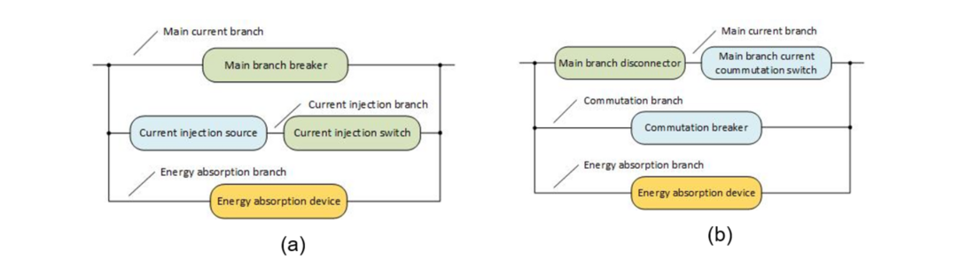
Figure 1 – Basic layout of (a) ACI and (b) MPE HVDC CBs
Operational experiences of HVDC circuit breakers
The operational experiences of HVDC CB installations in several multi-terminal VSC-HVDC systems are summarised. The respective systems and CB topologies, including their main characteristics and project-specific parameters are briefly explained. The recorded results of on-site CB performance tests are presented.
A total of 20 HVDC CBs have been installed in three multi-terminal VSC-HVDC projects in the world, all located in China, since 2016. Both ACI and MPE types of CBs are applied, and all of them use HV power IGBTs and vacuum mechanical switching devices as the switching components. MOSAs are used as energy absorption devices. The maximum operating voltage is 515 kV, and the rated and interrupting currents reach 3 000 A and 26 kA, respectively. The CB internal current commutation time is no more than 3–4 ms. Figure 2 shows the results of the planned onsite artificial short-circuit verification test for the HVCDC CB for Zhoushan five-terminal HVDC project.
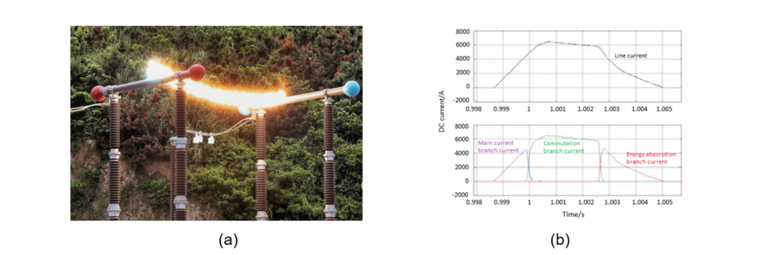
Figure 2 – On-site test of a CB. (a )The short-circuit arc created between HVDC poles, (b) Test waveforms illustrating fault current and branch currents
Modelling requirement of HVDC circuit breaker and HVDC system
Approaches for HVDC system and CB modelling are discussed. The discussion also includes modelling of HVDC systems for real-time hardware-in-the-loop (HIL) tests of CBs.
An HVDC grid generally includes components like DC CBs, control and protection systems, AC/DC converters, surge arresters, AC transformers, HVDC transmission lines, and HVDC cables. The simulation models proposed for these components depend on the types of studies to be performed. Detailed models of a CB are only required when analysing the CB itself, while simplified equivalent-circuit models can be used in system level studies. The key requirement for models of the protection and control system of an HVDC grid is to differentiate and locate the faults, and to then take necessary correct actions to protect the grid. Critical aspects of an HVDC control and protection system for CB-sizing studies include the response time and bandwidth, settings and dynamic characteristics, and synchronisation of different detections. The main challenges to real time simulation of a DC grid containing DCCBs are the large number of components in the circuit, the frequent change of circuit topology as components change their states, the presence of non-linear components, and the high number of logic signal exchanges.
Electrical requirements of HVDC circuit breakers
Key functional requirements of HVDC CBs and the system impact on them are analysed. A proposed methodology for defining the key CB parameters for a given HVDC system and protection strategy is then presented. The approaches that have been taken in both field installations and in academic studies are briefly introduced.
It is concluded that the fundamental requirements for HVDC CBs are low conduction loss during normal operation and fast operating time to interrupt both normal and fault currents. In some cases it is additionally important that the CB is able to reclose after a transient fault. Many aspects of the HVDC grid can impact CB requirements, including circuit topology, short circuit types and locations, protection strategies, etc. The content of CB rating studies is basically the same for all systems: fault type determination, CB and current-limiting design, identification of the worst-case conditions, optimisation of CB and current-limiting requirements, and final design verification. The actual approach for a given system will depend on the constraints and limits of that system.
Type test requirements of HVDC circuit breakers
Proposed ratings and type test requirements of CBs are summarised by referring to available standards and project-specific requirements of HVDC CBs. A detailed explanation is given of each proposed test and acceptance criteria. Additional test requirements are proposed that are unique to HVDC CBs.
Different CB stresses are relevant at various points of CB operation. The peak fault current occurs during the voltage-rise period of a CB, whereas the peak TIV occurs at the start of the fault-current suppression period. The rise time for the voltage between CB terminals is typically tens of microseconds or longer, depending on the system parameters and the grading circuit of a particular HVDC CB design. The presence and properties of a series-connected current-limiting reactor will affect the terminal-to-earth voltage stress of a CB. Due attention should be given to the design and verification of standard components, such as mechanical switchgear and energy absorbing elements, when they are used in a non-standard manner in HVDC CB applications.
Circuit for current interruption test of HVDC circuit breaker
A guide to the design and optimisation of test circuits for the current-interruption test of HVDC CBs is provided. Methods of applying post-suppression voltage stresses to different test circuits are then explained. Example circuits and test results for the current-interruption tests for both fielded HVDC CBs and those developed as part of major international research projects are briefly summarised.
Circuits for CB current-interruption testing should: pre-condition the CB to mimic the worst-case pre-fault condition; produce a test current equal to or exceeding the intended interruption current within the breaker operation time; supply the rated energy within the fault-current suppression time; and, supply the rated dielectric stress after fault-current suppression. These stresses can be provided using the AC short-circuit generator method, the charged capacitor method, or the charged reactor method. For reasonable and economical tests, practical testing methods such as unit testing, synthetic testing, and multi-part testing can be considered. The dielectric stress after current interruption can be supplied by either the charge trapping method or a separate DC voltage source.
Conclusion
SC B4 has been at the forefront of providing guidance on DC systems and power electronics. The potential readers of this TB are the engineers and academic professionals working in the areas of HVDC CB design and application. The contents of TB 873 may also be interesting to the professionals working on the various aspects of DC distribution networks and the working groups targeted for the creation or amendment of relevant national and international standards. TB 873 will benefit the readers in the following aspects:
- Becoming familiar with the HVDC technologies;
- Understanding HVDC CB technologies and design considerations;
- Becoming familiar with relevant national and international standards of HVDC CB;
- Using the proposed guide for CB configuration and fault management in the development of multi-terminal HVDC systems;
- Understanding the modelling considerations for key components of HVDC CBs and grids; and,
- Standardising the test of HVDC CBs by using the proposed type test parameters and test circuits.

Other Technical Brochures