Guide on the assessment, specification and design of synchronous condenser for power system with predominance of low or zero inertia generators
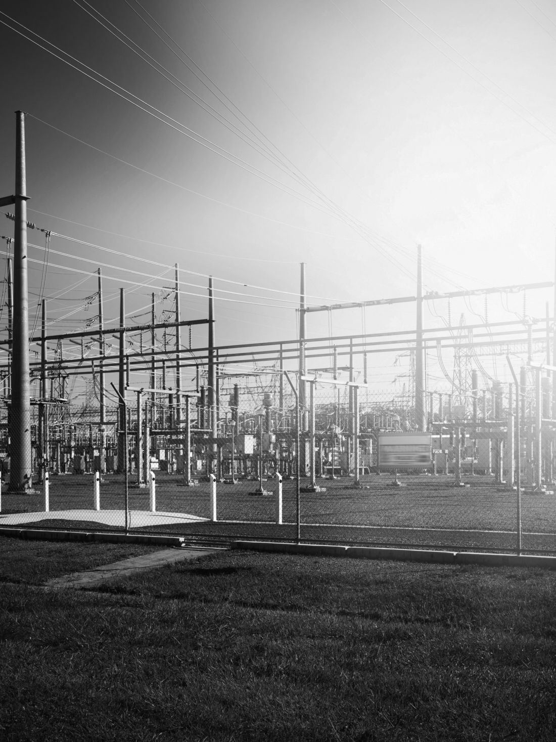
As part of carbon emission reduction initiatives, many countries have adopted policies to increase the installed capacity of renewable generation, based on Solar and Wind technologies, to either supplement or replace existing fossil fuel based power generation. Wind and Solar have been deployed en-masse at both transmission and distribution voltage levels.
Members
Convenor
(NL)
D.K.CHATURVEDI
Secretary
(AU)
L. SITU
L. ROUCO RODRIGUEZ (ES), B. MOORE (US), F. SPESCHA (AU), I. FERNANDO (CA), F. KOEHLER (GB), H. SHIMADA (JP), KONDRA NAGESH (IN)
Contributors
G. PRIME (FR), H. BIELLMANN (FR), L. MENG (SE), R. SINGH BAIS (IN), C. PAYERL (SE), K. CHAN (CH), M. SCHENONE (IT), S. KYNEV (US), R. BIONDI (IT), I. HIGGINSON (US), H. NAKAMURA (JP), A. ATALLAH (DE), J. SKLIUTAS (US), A. HASELBAUER (DE), Z. MENG (CN), A. KANNAN (DE), H. STEINS (DE), I. VOKONY (HU), P. GUGALE (CH), L. TACZI (HU), A. SHIGENAKA (JP), L. HAN (GB), A. YAMAMOTO (JP), M. GIESBRECHT (BR), S. MAEZAWA (JP), Y. KITAUCHI (JP), V. COSTAN (FR), T. VAN CUTSEM (BE), S. MARTINEZ VILLANUEVA (ES), G. LI (CN), O. AGAMALOV (UA), P. CHAY (FR), P. WIEHE (AU)
Introduction
System owners/operators, market regulators and wider stakeholders now increasingly appreciate the impacts that the ‘generation transition’ is having on the power system. The displacement of traditional synchronous machines with various forms of power electronic (PE) interfaced energy sources is contributing to fundamental changes in power system steady-state and dynamic behaviour, including
- Reducing levels of system inertia,
- Reducing levels of system strength,
- Reduced voltage regulation,
- Low level of fault current adversely impacted the protection system operation.
Scope and Methodology
The main objective of this WG was to produce a Technical Brochure (TB) in the form of an application guide which power network owners/operators and other parties can use to help determine network needs, understand the design and performance aspects of synchronous condensers and thereby specify their design requirements.
The scope of the guide was to give a comprehensive overview of the challenges faced by the power system due to reduced synchronous machine commitment, explain how synchronous condensers can contribute to addressing these challenges, and give case studies on the application of synchronous condensers in different scenarios to improve system operation.
Since the scope covers both machine and system considerations, a Joint Working Group (JWG) was established between study committees A1 Rotating Electrical Machines, and C4 Power System Technical Performance.
This guide has been developed by member experts from academia, power generation utilities, transmission system operators and generator manufacturers.
Description of the Technical Brochure
The first chapter of this guide appraises on the challenges arising in the modern grid due to high penetration of zero or low inertia power generation.
The second chapter covers the synchronous condenser performances and its significance to the power system stability and control. It gives insight into synchronous condenser design, impact of machine sub-transient reactance on system performance, and measures to improve the system inertia.
Case studies in chapter 3 discuss how synchronous condensers can help in the recovery of power supply during a transient disturbance. Another case study discusses the inertial support during a sudden load change. The performance of a synchronous condenser when installed in combination with a battery bank, has also been discussed in another case study.
Chapter 4 gives basic information on general construction and specifications of the synchronous condenser.
Chapter 5 appraises factors to be considered while converting existing units for synchronous condenser duty.
Chapter 6 shares some of the synchronous condenser installations along with a detailed list of installations worldwide. This chapter gives a brief on ten (10) different installations catering to various applications including retrofit solutions, flywheel, and clutch installations.
A flavour of the topics covered is given below.
Transition in power generation technologies
A significant increase in renewable energy, as well a gradual decrease in fossil fuel-based power generation is evident over the last decade. According to the latest report of UNEP ‘Global Trends in Renewable Energy investment 2020, renewable power additions required to meet Government targets with deadlines between 2020 and 2030 is 721GW. Renewable power addition planned by various countries between 2020 and 2030 is shown below in Figure 1.
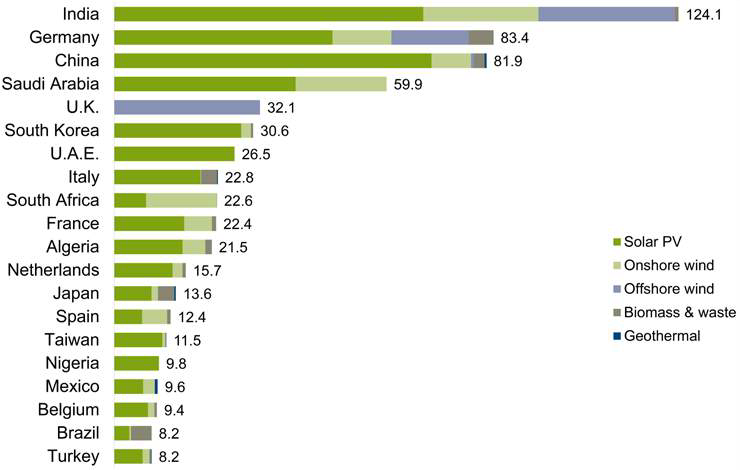
Figure 1 - Renewable Capacity addition (in GW) planned by countries between 2020 and 2030
Renewable power generation resources are often integrated to the power system using power electronic converters, which can be connected at transmission and distribution system voltage levels, generally through a step-up transformer unit as shown below in figure 2.

Figure 2 - Renewable power feeding to the grid through Inverter and step-up transformer
Issues with emerging solar and wind power generation
The variable and intermittent nature of the renewable energy resources presents several challenges associated with load/generation power balancing on the power system. Solar irradiance or wind speed acting as the “prime mover” for electricity generation results in an energy resource which can be difficult to dispatch reliably. This can lead to situations where peak electrical demand may not coincide with peak electrical generation in areas with high renewable energy penetration, thus making power system operators task difficult to balance demand and supply of electrical energy in systems.
The conventional power generation using synchronous generators with large rotating masses contribute power system inertia, reactive power support, and short circuit strength to the grid. These in turn help improve power system frequency regulation, voltage support, and overall power/voltage stability. Decommissioning of conventional power plants depletes the power system of the essential physical attributes of synchronous generators that helped in maintaining a stable and reliable grid.
Power System Performance
The power system inertia and electromagnetic strength are critical for a power system to be operated in a secure and robust manner. Traditionally, these two system measurements have been provided by large thermal and hydro synchronous generators, however, along with the rapid growth of the Inverter Based Resources (IBR) generation and a decreasing trend in minimum demand, less synchronous generation and a shortfall of inertia and system strength has been widely observed, significantly impacting the system security.
To ensure security of power system inertia and strength, many nations have introduced mandatory minimum system inertia and minimum fault level requirements.
Maintaining Minimum system inertia
The system inertia condition has strong implications on the system frequency control in the first few seconds after a disturbance and before the primary frequency response kicks in, therefore limiting the system initial rate of change of frequency (RoCoF). The largest single contingency is considered as the primary reference of the system minimum inertia specification.
Maintaining minimum fault level
System electro-magnetic strength (Short Circuit Withstand Capability) reflects the ability of a power system to maintain and control the voltage waveform at any given location following a fault or disturbance in the power system.
The power system minimum fault level is typically considered at the below four locations:
- The area remote from synchronous generation
- The area with high inverter-based resources
- The area close to metropolitan load centre
- The area close to synchronous generation centre.
Layout of Synchronous Condenser
Figure 3 below shows the configuration of a typical condenser installation. The installation has the following major components: (i) synchronous machine; (ii) startup system; (iii) excitation system; (iv) Generator Circuit breaker; (v) step up transformer; (vi) isolated phase bus ducts; (vii) auxiliaries; (viii) cooling system; (ix) control and protection. It might be built inside a building or outdoor.
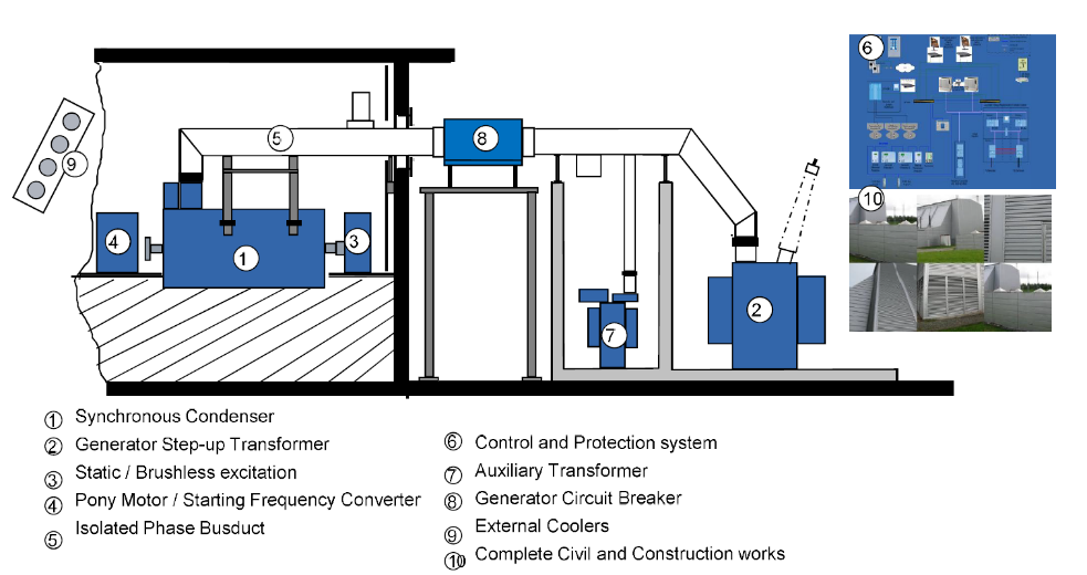
Figure 3 - Configuration of a typical Synchronous Condenser installation (without Flywheel)
Synchronous Condenser with Flywheel
Figure 4 below shows a schematic diagram of a synchronous condenser with flywheel. A battery storage system can also be added to the synchronous condenser assembly to provide the machine’s active power requirements for a specified time period, resulting in an “all-in-one” solution for grid stabilization.
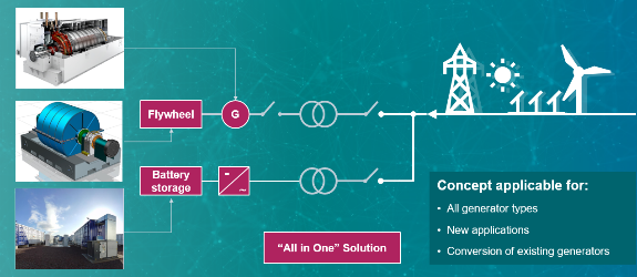
Figure 4 - Schematic diagram of Synchronous condenser with Flywheel (and battery storage)
Major Benefits of Synchronous Condensers over other solutions
Driven by large scale intermittent renewable development as well as the trend to retire conventional thermal generators, System Non-Synchronous Penetration (SNSP) has been unprecedented in many nations. As a result, maintaining power system security and ensuring sufficient essential grid services have become more critical. The synchronous condenser is considered as one of the key solutions to tackle this challenge. The following system essential ancillary services can be provided by a synchronous condenser:
- Fault current support to improve power system electromagnetic strength
- Physical inertia to limit the initial RoCoF in the first swing
- Reactive power support
- Fault ride through capability to ensure protection system operation.
Synchronous Condenser retrofit solution
While planning a conversion of a generator unit, the following factors need to be reviewed:
- Who will plan and initiate the conversion of the old generator unit?
- Relationship of conversion initiator agency with plant owner
- Does ownership need be transferred?
- Who will run the plant after conversion to a Synchronous Condenser?
- Who will bear capital expenses involved in the conversion?
- Who will carry out the operation and maintenance (O&M) after conversion and who will bear the O&M expenses?
In addition to the decision on the commercial aspects, one should also plan Residual Life Analysis (RLA) of the major electrical equipment and systems to be used after the conversion.
Conclusion
This application guide covers the emerging needs of grid operators and renewable power plant owners. It will help them to understand the technical capabilities of conventional turbo/hydro generators and limitations of power electronics-based renewable generation. The guide explains the reasons for the voltage stability and frequency stability issues on the electrical system associated with high renewable energy penetration. It analyses how the renewable energy addition will impact our power networks and discusses effective measures to address this by increasing inertia and effective measures to increase the fault level. The Sychronous Condenser based solution performance has been compared with alternative available FACTs devices. Performance analysis of available technologies for reactive support, inertia and short circuit power support establishes the superiority of the Synchronous Condenser based solution.

Other Technical Brochures