Installation of Submarine Power Cables
The use of submarine power cables is becoming more and more widespread due to for instance rapid development of renewable energy sources and the establishment of new interconnectors between countries and regions. The CIGRE Technical Brochure provides a common guideline concerning installation of submarine cable projects covering aspects like engineering, tools and execution. The guideline is appropriate for relevant parties such as power utilities, developers, installers, manufacturers, consultants, testing agencies, authorities and stakeholders.
Members
Convenor
(DK)
S. KRÜGER OLSEN
Secretary
(NL)
D.W. SNIP
Secretary
(IE)
P. O’ROURKE
J. M. ARGÜELLES (SP), M. BACCHINI (IT), A. BLANCHARD (first half) (FR), Á. FRANCÉS-PÉREZ (SP), R. GHIDONI (IT), D. GIUSTINI (IE), F. JAEGER (second half) (FR), K. JOHANNESSON (SE), M. JOHANSEN (DK), B. LADEGÅRD (NO), A. MACPHAIL (CA), M. PIWELLEK (DE), F. RONG (US), A. ZYMELKA (GB)
Corresponding Member
R.L. TANAKA (BR)
Introduction
The Technical Brochure (TB) focusses on the main installation aspects concerning the installation (laying, protection in and on the seabed and pulling to shore or onto an offshore asset) of submarine power cables. The technical brochure does not go into details about installation of accessories at offshore assets, electrical testing etc.
If cables and installations are optimally designed and installed, submarine cable systems should provide long periods with little or no maintenance – especially for cables with extruded insulation. If not optimally designed and installed, submarine cable systems can be a costly asset to operate, repair or even replace, especially when considering lost revenue due to forced outages. CIGRE TB 815 and TB 398 considers service experience of HV underground and submarine cable systems. From the information provided within, it is obvious that well protected cables have a significantly lower risk of of outages due to external damage. This underlines the importance of well-executed installation activities particularly considering the natural and anthropogenic threats that the installed cable will be subjected to over its lifetime.
The brochure is written as a guide for people who are interested in various types of submarine cable installation activities. Examples include, but are not limited to, the following:
- Interconnectors between countries or regions
- Export and inter array cables for connecting to offshore renewable assets
- Cables with power from shore to offshore oil and gas production platforms
- Cable installation in harbours
- Cable installation across rivers or other types of applications.
The power cables considered would typically be in the range of 30 kV to 550 kV for both AC and DC applications with various insulation types. However, the aspects covered within the TB would also be relevant for lower voltages as well as higher Voltages, as a reminder of the most important factors to be considered.
The aspects of submarine cable installation typically extend from the sea to onshore transition joint bays or manholes where they transition into an underground cable system. However, for some cases where the termination points are close to shore, submarine cables could be installed directly to the onshore termination points / switchgear etc, without transition joints.
Managing submarine cable projects and the installation thereof, may need to be handled differently from country to country. However, the principles pertaining to various disciplines and various fields of activity described in the TB, will be relevant for reference. Aspects closely related to submarine cable installation are also covered. Examples are interactions with government authorities and stakeholders for permitting/consenting purposes, insight into engineering practices and management of complex submarine cable installation projects. Aspects concerned with the operation, maintenance and decommissioning are discussed in the brochure. Submarine cable manufacturing is not included.
The activities described in the TB are intended to apply on a general level and not dictate how each individual submarine cable installation project is to be approached.
Consents and permitting
For submarine cable projects, obtaining the necessary permits and consents to construct and operate the cable system is essential but can often be a complex task. Generally, consents from affected / interested parties need to be discussed and agreed between the affected stakeholders.
It should be noted that some permitting authorities are not well versed on the technicalities of a cable installation and might object to proposals. These proposals which from a knowledgeable technical point of view, would normally be considered as being reasonable. It is important to understand the concerns of the permitting authorities and engage and discuss these concerns and furthermore propose acceptable solutions.
Permitting is typically given by authorities and they can setup rules to be followed, for example some countries may set up prescriptive installation methods or route corridor selection methods while others may allow for different options. It is noteworthy that at the permitting stage the actual installation method or route corridor may not have been finally selected and that these will be finalised only during the detailed design stage. Consenting is a more open process where the stakeholders can choose to agree or not.
For many project teams the matter of obtaining consents and permissions is a task running in parallel to the engineering work and other project tasks that are underway. The obtaining of consents and permits may be regarded as a side activity and may even be managed by a separate team depending on the project/company organisation. For the determination of optimum project outcomes, this approach can potentially be problematic. Indeed, the communication between the team applying for permits/consents and authorities/stakeholders may inadvertently limit possibilities for the engineering or installation teams to handle unexpected installation concerns or conditions. A good internal project/company communication process is essential during the consenting and permitting project phase to ensure full alignments between the different teams involved in the project.
Applying for permits and obtaining consents are typically done based on the “FEED and tender engineering”. It is important to highlight that not all detailed aspects of the projects would necessarily be known to the project team at this early point in time. Sufficient contingency should therefore be considered within the consenting and permitting task to allow for future changes at detailed engineering design and during installation activities.
The specific rights and protections as they pertain to submarine cables contained within UNCLOS (United Nations Convention on the Law of the Sea) and SOLAS (Safety Of Life At Sea), are mentioned such that they can provide a legal foundation for the submarine cable activities. Thus, developers are encouraged to make themselves aware of these rights and protections at the earliest opportunity so as to assist in the consenting and permitting processes.
Submarine cable installation engineering
The purpose of the engineering activities in a submarine cable installation project is to ensure a well-planned, optimised and coordinated cable installation. In addition, it is to ensure that the cable system(s) are installed correctly without damage, that the cables are protected as well as it is reasonably practicable and from an installation perspective, can operate with as few interruptions as reasonably possible throughout their lifetime. Engineering also needs to consider the technical, cost, and public safety aspects during the installation as well as during the lifetime of the submarine cable, together with external constraints imposed from authorities, stakeholders, and reduced impacts on the environment.
Engineering objectives and phases
The overall engineering process can be divided into project phases where certain key activities are carried out. Figure 1 shows a proposal for relevant engineering phases and activities for a submarine cable installation project, as recommended by this CIGRE Working Group B1.65. However, this can of course be handled in other ways, provided that the same aspects are covered.
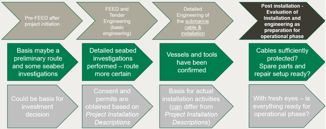
Figure 1 - Proposed engineering model for submarine cable installation projects
In this model, it is important to acknowledge that the engineering considered here focusses only on the cable installation activities. The engineering of the overall cable system is a separate activity not considered. The only aspects where this is not correct are:
- The mechanical aspects, where the cable mechanical design and the chosen installation concept, need to be aligned
- The cable ratings, where the desired requirements need to be made possible by the installation concepts
- The design of cable protection systems, where limitations concerning the installation must be considered when demonstrating that the design is feasible and functional.
Engineering studies
During the Pre-FEED, FEED and Detailed Engineering phases, several studies can be undertaken to engineer the cable routing and the means to protect the cable against external threats, as well as to assess the potential influence of the cable system may have on the surroundings.
Multiple studies can be executed for a project, depending upon the local physical conditions, on the requirements from authorities as well as on requirements and the overall approach of the project by the owner of the cable system. Executing specific studies, in preparation for the installation of the cable, will reduce uncertainties and risks during the following stages of the project as well as during the lifetime of the cable system. The studies can optimise the project itself, for instance from an execution (time) perspective and provide options to reduce life cycle costs.
Generally, the engineering studies can be updated or repeated when new and more accurate or detailed information becomes available.
Route investigation
tools and methods to get the submarine cables protected in or on the seabed. Typically, geophysical surveys are done first for a pre-determined corridor. These are often undertaken, using only a surface vessel without making sea bottom contact, except for grab sampling to help interpret side scan sonar and bathymetric results. The geotechnical survey typically follows the geophysical survey, where the results of the geophysical survey are used to determine where the geotechnical samples are to be taken. The geophysical and geotechnical survey data is then processed, integrated (ground-truthed), analysed, charts produced, and the optimal preliminary detailed route decided for the cable within this corridor taking into consideration factors such as the following:
- Water depth and temperature (if not obtained by other means)
- Thermal resistivity of the seabed along the route
- Underwater obstacles
- Seabed types: Hard rock, soft and hard soils, peat, and shallow gas pockets present in the seabed
- Seabed conditions along the route down to the required burial depth including thermal properties
- Underwater obstacles including various types of debris, exposed and sub-bottom boulders and (potential) unexploded ordnance (UXOs)
- Other subsea assets to be crossed
- Shipping lanes and channels, anchorages
- Slopes/steep inclines and cliffs
- High water currents
- High wave energy
All the above-mentioned factors contribute to the detailed route selection process and help to determine the approximate cable length. Geotechnical surveys should be used to ground truth the geophysical data and are typically undertaken at points selected using the geophysical survey data.
With the combined information from the geophysical and geotechnical surveys, a final route corridor for the submarine cable can be selected.
Cables can be protected to a degree against external threats such as demersal fishing, dragged anchors, lost cargo (for instance containers), etc., by burial of the cables into the seabed. Various other means of protection are for instance cable routing, rock placement, mattresses, and cable protection systems (for instance protective shells around the cable). All external threats which are considered likely to occur are to be quantified when designing the most appropriate protection requirements for the cable. The aim of probabilistic assessments like the Cable Burial Risk Assessment (CBRA) as well as of a Risk Based Burial Depth (RBBD) is to identify threats and hazards, evaluate potential probabilities and consequences. This would enable the establishment of risks to the cable and to provide recommendations for the most optimum and efficient risk mitigation or avoidance methods. It is noteworthy that results of a CBRA or RBBD study may determine that cable burial or other forms of protection is not required for some parts of the cable route. It may not for example be necessary to provide additional protection to the cables when water depths are beyond the reach of normal anthropogenic activities such as anchoring and demersal fishing. For some remote and medium voltage applications, the results of risk/benefit studies may also show that costs to repair could be less than costs to bury the cables in the seabed, so protection might again not be cost-justified.
Installation tools, vessels, and considerations
For the installation of subsea cables, various equipment and vessels can be used to prepare the seabed for the installation of the cables, to lay the cables and to provide protection to the cables. The most common way to provide protection to the cable is by burial of the cables into the seabed, where and when reasonably possible.
Multiple tools are available on the market to clear the seabed of obstructions as well as to install subsea cables. Out of Service assets on and in the seabed may also need to be addressed. Out of Service telecom cables are typically cut away and laid aside with the ends secured. Out of Service pipelines are typically left in place. For those assets that are being left in place and for the crossings with other In Service assets, crossing methods and structures will need to be agreed and implemented with the asset owners. This to ensure that the minimum required vertical separation between assets over their lifetime is provided and maintained. Also, this should ensure that optimum levels of protection of the subsea cable is provided at those sections where the cable cannot be buried into the seabed. Grapnels and other tools may be used to clear other obstructions from the route, which cannot be avoided by micro-rerouting of the subsea cable.
For cable installation, Cable Lay Vessels and Cable Lay Barges would have to be defined, identified and deployed as necessary. Barges and shallow draft vessels can access areas with low water depth, but are typically more susceptible to adverse weather conditions, particularly to waves and swell. The larger offshore going cable lay vessels can continue to lay cable under much worse weather and sea conditions but might not be able to approach the selected land fall location sufficiently close.
For the burial of the cables into the seabed a wide range of cable burial tools are available in the market. Three general requirements can be identified for these tools, which allows for a broad classification of these tools. Firstly, the burial tools have to be able to penetrate into the seabed to the required depth. This can be achieved by ploughing, by cutting / fluidising the seabed with water jets, by cutting using a chain cutter or a wheel cutter or by combinations of these techniques. Secondly, the cable would need to be placed / buried to the required burial depth. That could be achieved by allowing the cable to sink down under its own weight into the trench. This however can be hampered by seabed which is insufficiently fluidised, and which does not let the cable sink to the required depth. The cable could alternatively be guided down through an enclosed stinger, blade, or similar, which keeps the cable free from interaction with the soil until it has reached the required burial depth. This however might introduce potential external forces acting on the cable, for instance by a depressor. Those forces should be calculated to ensure that these forces will not compromise the integrity of the cable. The third function of the burial tools is their ability to move along the cable route whilst burying the cable. This can be done by being towed over / through the seabed on skids by the cable ship, by manoeuvring using its own power by thrusters or tracks or by being suspended from the installation barge or vessel. A wide variety of combinations of these three functions are available on the market, each with their own benefits and potential risks.
Execution of submarine cable installation
During the execution phase the main field works are performed and the cables are installed. First of efforts are undertaken to prepare the execution of the cable installation activities. This includes gathering the inputs from project planning and permits, risk assessments, EHS, method statements or management documents relevant for the works including identification of the main functions participating in the project and more. Also considered are the steps to be undertaken when mobilising the installation spread in order to ensure that the equipment to be used during the installation campaign is in good operational condition and able to be operated under the conditions expected. Remedial methods are confirmed for the situation where the installation tools do not perform as expected in the actual seabed.
For cable installation projects where shore pull-in are required, onshore works need to be scheduled with sufficient margin to assure they will be finished before the laying activities, but it is especially important when the landing is designed by trenchless solutions and with pre-installed ducts in trenches.
The laying operations are often a critical part of the project. Before commencement of a laying operation, it is necessary that the seabed preparations are completed (potential obstacles removed, UXO removed after an appropriate inspection and identification, in accordance with the rules of each country for managing those potentially dangerous elements) and crossing prepared etc.
The cables can be damaged not only due to external aggressions caused by anchoring or demersal fishing activities, but also due to mechanical fatigue / failure, particularly if the cable experiences free-spans (suspensions) after laying. For this reason, further remedial works may be needed to avoid / reduce those free-spans and avoid future cable damage.
It is also worth noting that during the execution of submarine cable installation activities, unexpected situations can occur, forcing the installation to be temporarily suspended. The cable might need to be cut, the end sealed and temporarily deployed to the seabed. The installation vessel would then be in stand-by until the conditions are appropriate to continue the campaign in a safe way. On these occasions, it is likely that an in-line joint will need to be made to integrate to the now recovered cable that was temporarily deployed to the seabed before suspending the operations.
The installation activities will conclude with the commissioning tests (also called after, or post -installation verification and testing). The aim of these tests is to ensure that the cable has been properly installed without damage and that it is ready for normal operation. The as-laid cable route may need to be surveyed to provide additional information required for the preparation of the final documentation to be provided to the client. The as-laid / as-built information of the submarine cable is to be consolidated and circulated to all those who need to be informed about the position of the cable on / in the seabed.
Operation, maintenance, and decommissioning
Maintenance during operation can be categorised as being either planned or unplanned (see also CIGRE TB 825).
Planned maintenance is a scheduled activity and it’s aimed to minimise risks of cable failure. Knowing that the majority of cable failures can be due to severe sea activity and external anthropogenic activities (demersal fishing and anchoring practice etc) means that the reliability of the submarine cable system begins at the design stage. Checks and remedial works for the mechanical protection of the submarine cable is considered part of the planned maintenance activities, therefore survey campaigns and landing inspections with associated expected reburial, removal of additional cover or rock berm reinstatement might be considered to be part of this activity.
Unplanned maintenance is required following a cable failure or cable damage, urgent reinstatement of protection / reburial activities associated with unexpected reduction of cover, or even cable exposure of the cable on the seabed. In case of a fault, after locating it, repair activities commence (see also CIGRE TB 773). Definition of procedures for this delicate activity and adherence to these are essential to reduce the timing and resources required. A cable repair can range in complexity and time from some days to several months. The difference stemming from various factors such as, contingency planning, spares availability, vessel availability, cable type, complexity of the repair, location of the repair, burial / protection status of the cable, time of year (weather), insurance mechanisms, criticality of the cable asset.
Before a repair can begin the cable needs to be made safe, typically by grounding both ends. Seabed data and depth of burial data is to be reviewed and assessed to determine how the cable can be exposed in the area where a repair is required. It is also very important to check possible old and new crossings and if these crossings are above or underneath the asset. Depending on this condition, the engineering for the repair campaign can be affected fundamentally. The cable will need to be cut on the seabed and recovered to deck. When excavating / de-trenching the section of cable that is to be re-used during the repair operation, it is essential that the Critical Cable Handling Parameters (CCHP) of the cable are respected. Failure to do this can result in a repaired cable faulting again within the disturbed / recovered area. Planning of various repair scenarios along with a certain degree of engineering should preferably be a part of the asset owners contingency planning and repair preparedness. Being prepared increases the possibility of a shorter outage period and associated cost savings. After the repair and testing has been completed the cable system would be formally handed back over to operations. The energisation would then be handled as normal by the operational staff.
Consideration regarding the cable system decommissioning is discussed in the TB. When submarine cables have become obsolete, it needs to be decided whether they are best to be left in place or if they need to be removed. The removal of the cables after end of service may even be part of the requirement original permissions obtained before installation. The complexity of removal of cables can depend on the installation methodology used and with the potential need for the use of special recovery vessels and equipment. The potential cost to retrieve the cables should be considered. The environmental impact of the removal can in some cases be assessed to be worse than leaving the cables in the ground/seabed.
When submarine cables are not in service anymore, the cable routes on naval charts may be marked as out of service or, after removal of the cable, be deleted. Depending on cable type further work may be needed. Fluid filled cables may need special treatment ensuring that the cables are not able to leak fluid into the sea. Specific methods for fluid filled cable decommissioning are discussed in the TB.
The decommissioning of cables will be addressed in more detail by CIGRE Working Group B1/C3.85, which started in the beginning of 2022.

Other Technical Brochures