Basic principles and practical methods to measure the AC and DC resistance of conductors of power cables
Transmission systems, such as high voltage overhead lines and cables, are an integral part of the power grid. Due to large currents and their electrical resistance, the inner or main conductor of such a cable or transmission line is responsible for most of its electrical losses, as evidenced by its heat dissipation. This brochure deals with the accurate resistance measurement of power cable conductors, typically used in AC and DC transmission systems.
Members
Convenor
(CH)
B. DARDEL
R. SUCHANTKE (DE), C.J. LIU (US), D. WILLÉN (DK), P. DE BRUYNE (CH), Z. LI (CA), A. FUSTIER (FR), E. BEAUGUITTE (FR), S. GROßMANN (DE), M. SJÖBERG (SE), R. PLATH (DE), L. MUNTEANU (US), T. AARIANS (NL), G. SCHRÖDER (DE), I. BOEV (CA), T. ISRAEL (DE), C. MICHELSEN (DK)
Introduction
Conductors for insulated cables are classified according to their size defined by their electrical DC resistance in IEC 60228. Nevertheless, most of the power lines are used in AC mode, where for large conductors for cables and overhead lines, AC losses (such as skin effect and proximity effect) may lead to important load capacity reductions. These are dependent on the conductor design, thus the qualification of AC conductor resistance becomes a critical aspect of cable design. Though the subject has been studied theoretically in detail, and different methods for measurement of AC resistance have been proposed in CIGRE TB 272, no specific measurement setup or method is presently prescribed in the IEC standards for conductor resistance measurements, even for DC.
In AC mode, a phenomenon such as skin effect modifies the distribution of current in the conductor and hence leads to increased losses. Conductor design becomes critical for large cross-sections, where these effects are important—the AC resistance at 50 Hz is for example 60 % higher than in DC for 2000 mm² solid copper conductor. Reduction of the AC resistance and hence of the associated losses can, for example, be obtained using insulated wires.
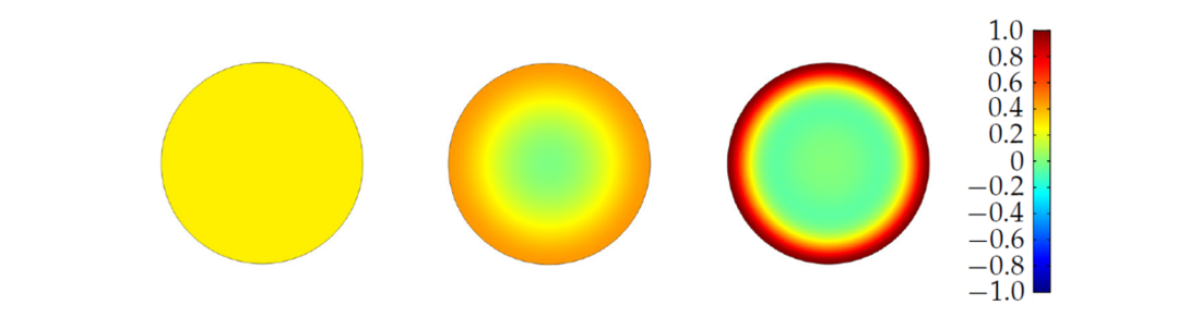
Figure 1 - Normalized in-plane current density in a circular conductor cross section; from DC (left) to increasing frequencies (to the right)
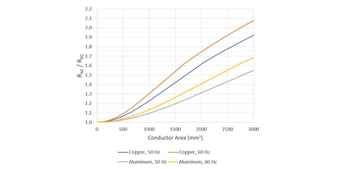
Figure 2 - Resistance ratio for different cross-sectional sizes of a cylindrical copper conductor
Characterization of the AC electrical resistance of large conductor is then required for design and qualification purposes.
The brochure gives a general introduction to the topic by discussing the theoretical background of AC loss mechanisms and describing critical influences in the electrical measurement of complex conductors. State of the art measurement practices are shown, both for DC and AC measurements. Additionally, best practices of connection systems and temperature measurement and stabilization are discussed. Also, the results of the round robin test performed during this research, both of reference conductors and different power cable conductors, are presented. The focus of this document lies on accumulated knowledge from literature and own research conducted by the group. The reader can find the proposed recommendations for an accurate measurement of AC and DC resistances, using the electrical method. It details the requirements on the environment and equipment, the performance check of the measurement system, the preparation of the conductor sample and the complete measurement setup.
Particularities of Electrical Measurements at AC
The electrical measurement method uses electrical signals, namely the measured voltage drop and the total conductor current, to determine the AC resistance of a conductor section. Typically, a current path and a voltage measurement loop are present in the setup. The closed current path delivers the test current to the conductor under test (CUT). The voltage loop is composed of two voltage lead wires from measurement system to the voltage tap-offs—their connection to the CUT—the CUT itself and the inner resistance/impedance of the measurement system.
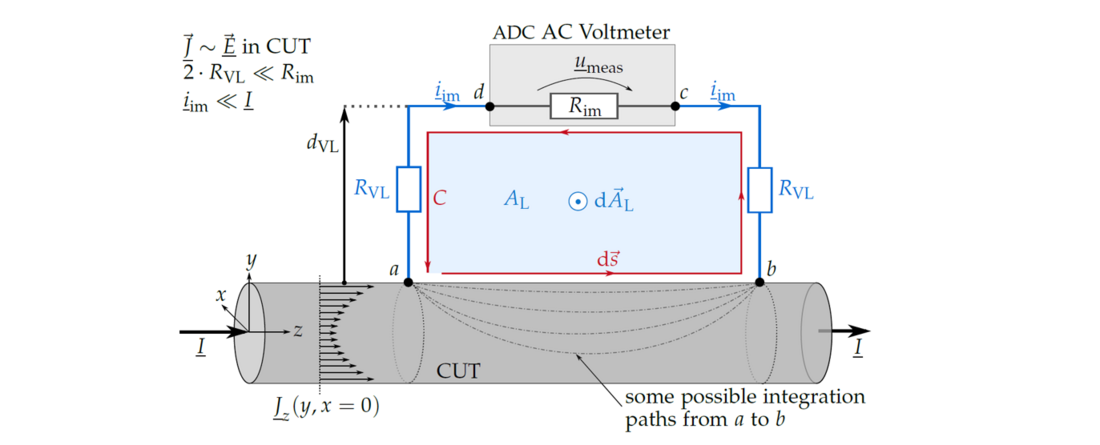
Figure 3 - Measurement setup on a cylindrical solid CUT highlighting the voltage leads (blue lines) and voltage loop (blue area)
It is important to note that at AC, the measured AC resistance can depend on the arrangement of the voltage loop as it can be influenced by complex magnetic fields penetrating the voltage loop. The measured resistance is composed of:
It includes the electric field inside the conductor, which is linked to the current distribution inside the sample and it includes the magnetic field formed by the voltage lead wires and sample. It is usually normalized to the measurement length and hence given in per-unit. The current distribution inside the sample and the magnetic field surrounding the CUT are influenced by many aspects of the measurement setup:
- return conductor setup (the return conductor, is the conductor which brings the current back to its source)
- conducting material in the surrounding (e.g., metallic parts in the support structure, wall or floor)
- current contact system (how is the test current injected into a complex conductor)

Round Robin Test
Four samples were measured by 8 different laboratories:
- aluminium Milliken conductor cable: 2000 mm²
- copper Milliken conductor cable: 2500 mm²
- copper rod: 50 mm outer diameter
- copper pipe: 50 mm outer diameter; 40 mm inner diameter
DC as well as AC measurements were conducted at 20 °C and, where possible, at 90 °C and compared with theoretical value calculated from IEC 60287 (shown for 50 Hz at 20 °C in the following figure). It shall be noted however that there is no analytical solution for Milliken conductors and that the IEC 60287 values are only empirical approximations for complex designs. The actual performance depends on the detailed conductor design and manufacturing process. Hence, AC resistance cannot be deduced from some empirical formula and, a measurement is necessary for each conductor design.

Figure 4 - Lab measured AC resistances deviation from IEC calculation @ 20⁰C
The discrepancies between the measurements in the different laboratories are larger than the reproducibility one would hope for, and probably expect on a single system. This can be explained by the fact that the measurements were performed using different configurations, confirming the sensibility of the measurement to the setup.
Nevertheless, measurement on well-defined and rotationally symmetric samples (rod + pipe) show less variation. This on the other side reflects the inherent difficulty of AC loss measurement and of the measurement on complex cable conductors. It shows how important it is to follow specific guidelines and recommendations to have comparable results, when performing AC and DC resistance measurements.
Recommendations
The brochure gives recommendations on the different possible setups for an accurate measurement and the influence of the different parameters such as
- sample preparation
- surrounding
- return conductor
- voltage loop
- connections for current injection
- voltage tap-offs
- thermal stability management
Also, it provides a new method to interpret and classify results, which depends on measurement data and thereby stresses the necessity of a measurement.
Conclusion
From the analyses and investigations performed, it can be concluded that DC and especially AC resistance measurement is a difficult task, if the desired accuracy is high. Many influencing factors need to be considered, to be able to accurately rate a complex conductor design, such as a Milliken conductor.
The brochure establishes well defined setups and allows users to perform accurate measurement on their conductor(s) under test, accounting for influences of different conductor designs choices.

Other Technical Brochures