A three-terminal LCC-HVDC network upgraded from a point-to-point link in China
The Guizhou-Guangdong-I (GG-I) project in China is a line-commutated-converter based high-voltage direct-current (LCC-HVDC) link which has been transferring power from Guizhou Province to Guangdong Province for about twenty years. However, to achieve net-zero emission, the use of clean power resources and decommissioning of existing coal power plants are speeding up. In Guizhou province, the coal power supply is declining and the hydropower supply in Yunnan province is increasing. At the same time, to achieve the flexible allocation of electric power across regions, an upgrade plan of the GG-I HVDC project has been proposed to extend it as a three-terminal HVDC system to transfer more hydropower amongst the Yunnan, Guizhou and Guangdong Provinces.
by Qi GUO and Mengjun Liao, Electric Power Research Institute of China Southern Power Grid, China
Upgrade Scheme
Originally, the GG-I HVDC project was a ±500 kV point-to-point LCC-HVDC link with a capacity of 3000 MW. It is a bipolar system with electrodes. The overhead line is 860 km. The Gaopo rectifier station locates in Guizhou Province and the Zhaoqing inverter station locates in Guangdong Province. The upgraded three-terminal system (called LuGaoZhao HVDC) is shown in Figure 1. In the system, a 3000 MW rectifier station is newly constructed in Luquan in Yunnan Province. The length of the new HVDC transmission line connects to the Gaopo station is 342 km. The project was fully commissioned in June 2020.
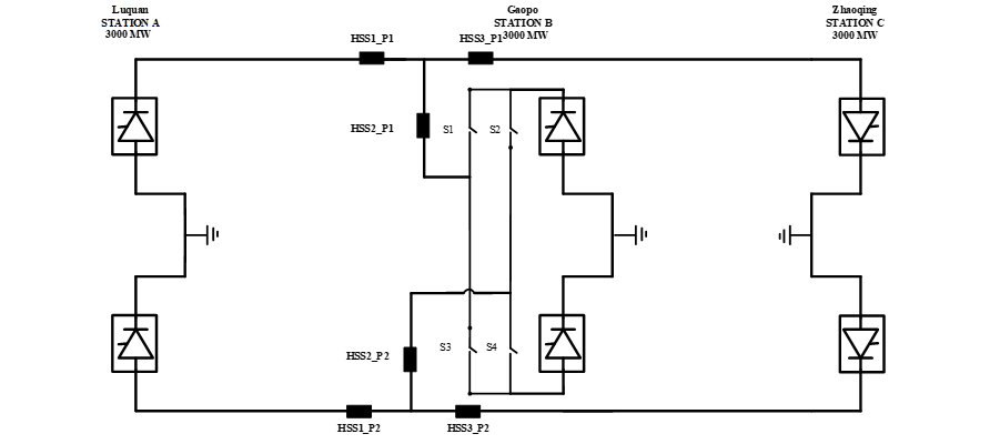
Figure 1 - The circuit of the LuGaoZhao three-terminal HVDC system
To achieve the flexible operation of the three-terminal HVDC system, the main circuit of the Gaopo converter station has been upgraded: a common DC bus, high-speed switches (HSSs) and polarity reversal switches are added. The common bus in the Gaopo station connects the two HVDC links. The HSSs are used for switching on and bypassing the converters. The polarity reversal switches can change the positive and negative polarities of the Gaopo station to operate as both rectifier and inverter. Other main equipment is not upgraded but the Control and Protection (C&P) system and measurement devices are. There are eight operation modes of the system, which are shown in Table 1.

*Rec. - Rectifier, Inv. - Inverter, CC - Constant Current, CV - Constant voltage
Table 1 - Eight operation modes of the LuGaoZhao three-terminal HVDC system
Main Control Functions
Control modes of the three converter stations
As shown in Table 1, the upgraded system can operate in either an HVDC link or a three-terminal system. In the HVDC link mode, the rectifier station is in the DC current control and the inverter station is in the DC voltage control. In three-terminal modes, Stations A and B are in the DC current control and Station C is in the DC voltage control.
Start-up Sequence of the three-terminal system
Station C will firstly enable the Firing Plus (FP) after receiving the deblocking command from the control centre. Station A will then enable its FP after receiving both the deblocking commend and the signal that Station C has been enabled. As for Station B, its FP will be enabled 1 s after receiving both the deblocking commend and the signal that Station C is enabled as a rectifier. Otherwise, Station B will be enabled 1 s after only receiving the deblocking commend as an inverter.
Converter switching-off and switching-on control
In the case that one of the stations is out-of-service, the three-terminal HVDC system can be changed to point-to-point operation. The converter in/quit control is designed for this process. When a converter is out-of-service, a command of stopping the three-terminal operation will be executed. If this is a rectifier, it will be Forced Retarded (FR, increasing the delay angle of the rectifier) to reduce DC current and then the relevant HSS in Gaopo station will be switched off under the minimum DC current condition. The firing angle order will be released again once the C&P system receives the switching-off signal to recover the DC voltage and current. Moreover, a three-terminal stop command will be activated if the HSS operating signal is not received in a certain time to prevent the quitting failure. Similarly, the switch-on of a converter needs that the FR firstly reduces DC current and then releases the firing angle order after knowing that the HSS has finished the switching-on operation.
DC Line Fault Detection
The DC side has two segments: Line 1 from Station A to Station B and Line 2 from Station B to Station C. The HSS is able to isolate the faulty segment under DC line fault detection. In the upgraded C&P system, the DC line fault detection is implemented in coordination with DC line protection and the direction of the fault current.
The DC line protection at Station A covers the whole range of Line 1. Station C covers the whole range of Line 2. Station B has two individual DC line protections and directional detection of the fault currents for Line 1 and Line 2. For example, if a fault occurs in Line 1, the DC line protection of Stations A and B will be active and the direction of fault current for Line 2 will be inactive.
DC Line Fault and recovery
Travelling wave protection and DC line derivative protection are used in this project. If a line fault occurs, the DC line protection acts and trips FR. Generally, 400 ms or 450 ms of FR is set for DC fault clearance. Hence, there is enough time for DC fault detection. In this strategy, the system recovery is the same as the traditional HVDC link for temporary DC fault. However, it should be noted that another FR will be needed to isolate the converter with the faulty DC line in case of a permanent fault. For example, if a permanent fault occurs in Line 1, Station A and Line 1 will be isolated. This will take one more time of FR for switching-off Station A, which may cause DC power ramp down and system disturbances.
Coordinated distribution of DC power amongst the three terminals
When the power order at one station is changed, a decision must be made on how to reschedule the power with the other two stations. Considering that the hydropower generation at Station A is environmentally friendly and cheap, the control system gives a higher priority to ramp up the power over the Station B with the coal power generation. For example, Station A will make a power ramp-up through the Frequency Limit Control (FLC) at Station C. Station B will take the rest power if Station A has reached its maximum.

Off-site Real-Time Simulation Tests
A real-time simulation platform has been constructed with the C&P cubicles hardware-in-the-loop (HIL) to implement off-site tests before commissioning. The off-site tests involve two phases of Functional Performance Test (FPT) and Dynamic Performance Test (DPT). It took almost 10 months to complete all the tests, involving more than 1500 items. Two cases of system start-up and converter switching-off are presented.
Start-up (deblocking) of the three-terminal system
Simulation results of the start-up processes of the three-terminal system are shown in Figure 2. The DC currents are ramped up at Stations A and C first. Station B is enabled 1 s later.
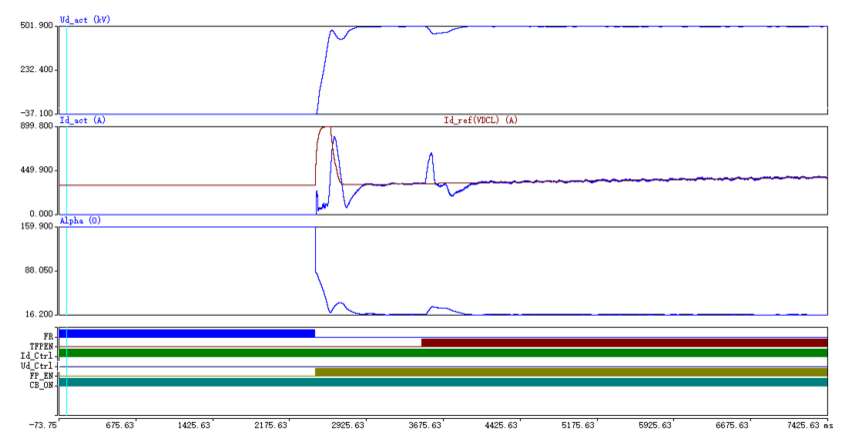
a. DC voltage, current, firing angle and status of Station A
Figure 2 - Real-time simulation results of deblocking the three-terminal system
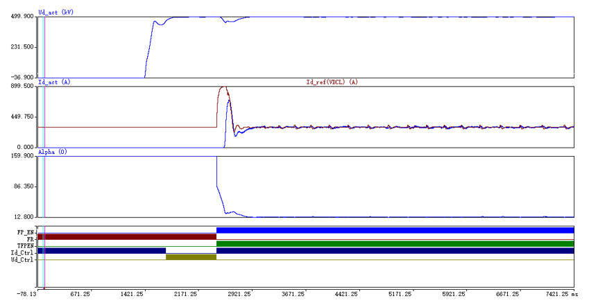
b. DC voltage, current, firing angle and status of Station B (Rectifier)
Figure 2 - Real-time simulation results of deblocking the three-terminal system
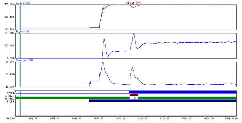
c. DC voltage, current, firing angle and status of Station C
Figure 2 - Real-time simulation results of deblocking the three-terminal system
Converter switching-off
In the operation mode of L,G-Z, if a DC fault occurs in the positive pole of Station A, Stations B and C should be able to remain in operation after the faulty converter is switched off. Simulation results are shown in Figure 3.
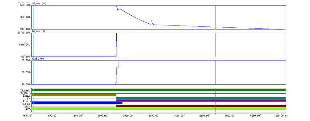
a. DC voltage, current, firing angle and status of Station A
Figure 3 - Real-time simulation results of converter fault on the positive pole Station A
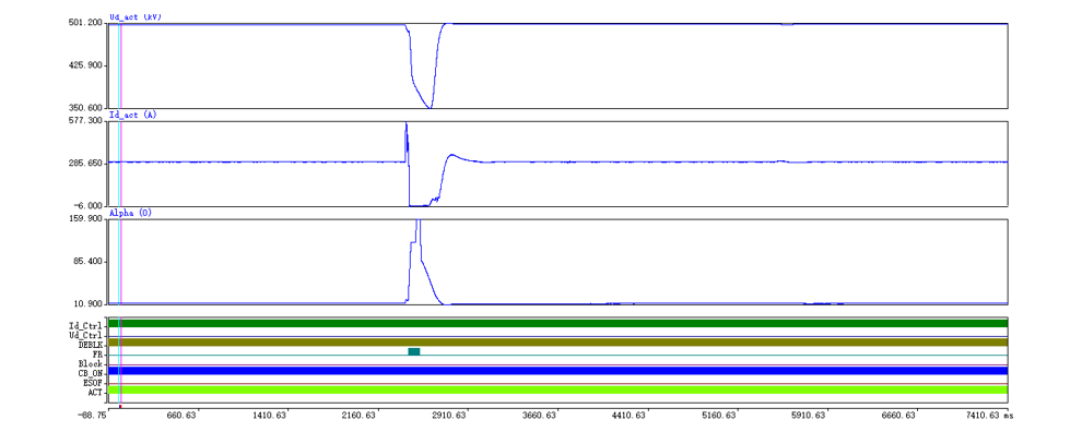
b. DC voltage, current, firing angle and status of Station B
Figure 3 - Real-time simulation results of converter fault on the positive pole Station A
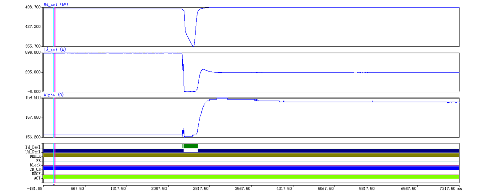
c. DC voltage, current, firing angle and status for Station C
Figure 3 - Real-time simulation results of converter fault on the positive pole Station A
Comparison of Simulation Results with On-site Records
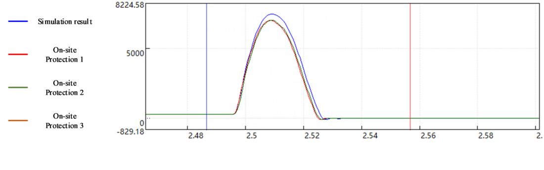
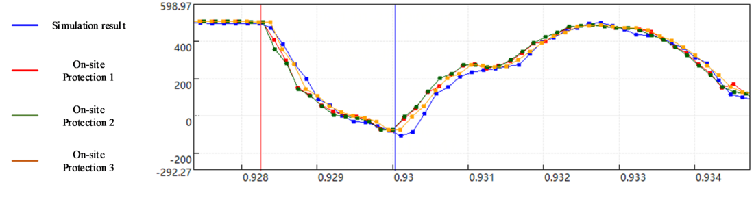
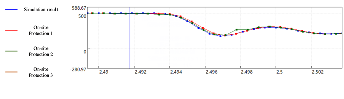
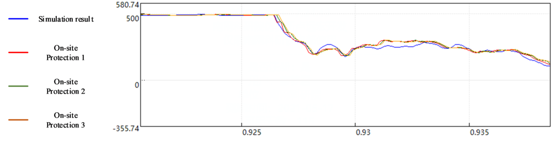
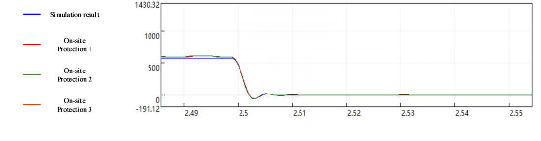
Simulation tests of a DC line fault in Line 1 have been done before the commission of the project. The two records are compared at the same time domain for C&P verification and model validation. The blue curve below is the simulation result. The red, green and orange curves are on-site records. The comparison shows that simulation results and on-site records match well. It proves that the simulation platform has high accuracy and the simulation results are reliable and can reflect the fault characteristics and C&P responses.
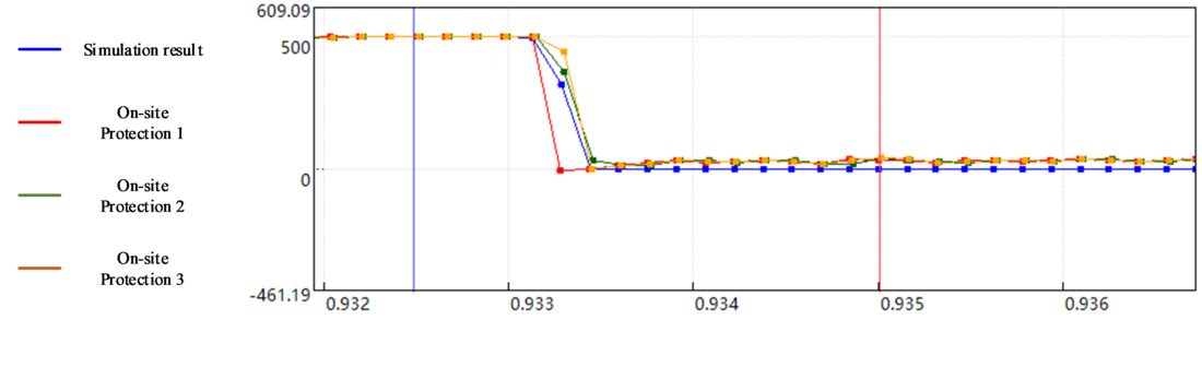
a. DC line voltage of Line 1 at Station A
Figure 4 - Comparison of simulation results and on-site records for a DC line fault
b. DC line current of Line 1 at Station A
Figure 4 - Comparison of simulation results and on-site records for a DC line fault
c. DC line voltage of Line 1 at Station B
Figure 4 - Comparison of simulation results and on-site records for a DC line fault
d. DC current of Station B
Figure 4 - Comparison of simulation results and on-site records for a DC line fault
e. DC line voltage of Line 2 at Station C
Figure 4 - Comparison of simulation results and on-site records for a DC line fault
f. DC current of Station C
Figure 4 - Comparison of simulation results and on-site records for a DC line fault
Thumbnail credit: Road Ahead on Unsplash
Suggested content