Guide to Develop Real-Time Simulation Models for HVDC Operational Studies
Technical Brochure 864 is intended to provide general guidelines for the development of real-time simulation models (RTSMs) for HVDC operational and specification studies.
Members
Convenor
(CN)
Q. GUO
Secretary
(CN)
P. WANG
M. LIAO (CN), Z. SONG (UK), T. TIMM (DE), Y. ZHANG (CA), Y. VERNAY (FR), Z. WANG (CA), A. ZAMA (FR), W. ZIAD EL-KHATIB, W. WANG (CA), H. RAO (CN), J. JARDINI (BR), S. SANTO (BR), D. LIU (CN), G. LI (UK), F. ZERIHUN (BE), Y. ZHU (CN), D. SHEARER (SE), A. AL-MUBARAK (SA), A. SAUTUA (ES)
Corresponding members : D. MENZIES (CA), C. KRIEGER (DE)
Introduction
Real-time simulation (RTS) is often used to perform hardware-in-the-loop tests of HVDC control and protection (C&P) systems to verify its compliance with the technical requirements prior to its site implementation. In the last decade, the RTS has been extensively adopted as a useful method of performing HVDC tests and system studies in many phases of real projects. It has been carried out for both new and refurbishment projects in the phases of design, construction, commissioning as well as in-operations.
The effectiveness of RTS is especially pronounced in situations, where the modelling of a complex C&P system containing many nonlinear interactions for an accurate representation can be a challenge. By connecting with the physical C&P systems in the simulation loop, or with a replica of the real C&P system, the functional and dynamic performance of a real C&P system can be studied, tested and verified on a real-time simulation platform. .
Although each HVDC system has its unique feature, there are similarities in terms of RTS modelling methods, constructing a replica and performing RTS related studies. Hence, the topic of this technical brochure (TB) is to provide general guidelines for the development of real-time simulation models for HVDC operational studies to evaluate HVDC C&P design and performance and complex system issues associated with HVDC system and connected AC system.
Typical studying scenarios for HVDC systems in RTS
One must know that there is no universal RTSM for all types of HVDC operational studies. Suitable RTSMs must be chosen to meet the special requirement of different study scenes. The brochure presents some typical HVDC studying scenarios, in which RTS is applied effectively.
The design and engineering of C&P functions are an integral part of the overall C&P software design. The result of the joint studies and software development process is the plant control and protection software. This software is further evaluated, validated, and – depending on the overall development process - optimized in combination with the hardware control cubicles. In the so-called off-site test phase, it is demonstrated that the actual control and protection system performs by RTS in compliance with the technical specification.
The post-disturbance and mitigation studies of HVDC projects are to analyze and identify any incorrect C&P logic or parameter setting that causes maloperation, trip or any unwanted performance of the HVDC link. In the study, the actual field events will be simulated on a platform consisting of the real-time simulator and HVDC C&P replica. The proposed modification of HVDC C&P functions can be verified and used to improve HVDC performance in a similar disturbance. These simulations take place during the operation life of an HVDC project, aiming to avoid HVDC control and protection anomalies, incorrect or faulty operations during faults or disturbances.
The connected AC system supplies commutation voltage for the LCC HVDC converter to accomplish AC-DC-AC conversion and realize power transfer. There may be some interaction issues between HVDC and nearby AC systems, both in the sending end and receiving AC power systems. It is a specific and complex issue coupling with various power system equipment in different system conditions. Dynamic control of power electronic devices such as HVDC, SVC and STATCOM can interact via the AC system in a manner that cannot be foreseen. Furthermore, some HVDC C&P functions like the Voltage Dependent Current Order Limiter (VDCOL) or a coordinated control, which was designed to coordinate the HVDC operation with other nearby equipment such as an SVC/STATCOM, depend much on the conditions of the connected AC system. An AC system interaction study can be prudent to ensure system stability.
As an important technical means of long-distance power transmission, inverter stations are generally located in power load centers. The increasing usage of electrical power, especially in developing countries such as China, Brazil, and India, has led to configurations wherein multiple HVDC links are now appearing in electrical proximity. An understanding of such systems must evolve from independent single HVDC infeed system assessments, such as multi-HVDCs commutation failure.
Real-Time Simulation Modelling for HVDC Equipment
The real-time simulation models are based on Electromagnetic Transient (EMT) theory. As the EMT theory and algorithms are well documented in many classical publications, the only focus on the special techniques used in modelling HVDC equipment and systems for real-time simulation.
There are two different approaches to represent the Line Commutated Converter (LCC) HVDC valve groups. One approach is to adopt the same method as treating the synchronous machine or transformer and model the valve group as one specific model in the simulation software. The other approach is to represent the valve group as a set of individual branches. These branches are then included as part of the equations of the entire system. Both approaches have been used in research as well as commercial real-time simulators.
For a Modular Multilevel Converter (MMC) model, it require a significant amount of computation power for large numbers of Submodules, which can only be achieved by FPGAs. The surrogate networks and other equivalent network methods facilitate the efficient real-time simulation of MMC valves with large numbers of Submodules (SMs) on both processors and FPGAs. The most recent development is the generic MMC model on the FPGA. The generic model is able to model all IGBT firing combinations in an MMC submodule. Thus, a variety of the MMC internal faults can be studied. Meanwhile, it is capable of modelling the different parameters of individual SMs, including faults inside the legs and between the legs and ground.
The converter transformer model, in particular for the LCC scheme, is combined with the valve group for two reasons: to save computation resources and to provide gamma measurement to the controllers which require it. In most of traditional EMT theories, transformer saturation is implemented by either a variable inductor or an injection tapped on each terminal of a transformer. It is a common understanding that the method with variable admittance is numerically more stable than the method with injection. Recently, demands to model the DC bias in transformer saturation have led to a more sophisticated transformer modelling algorithm. The algorithms based on magnetic circuits solution have advantages to model this type of phenomenon with higher accuracy. One of the successful models called the Unified Magnetic Equivalent Circuit (UMEC) model is available on some real-time digital simulators.
The accuracy of the modelling of transmission lines is a very important part of the close-loop testing of HVDC systems. The most commonly used frequency-dependent transmission line model is the J. Marti model based on the modal domain concept. It is assumed that the transformation matrix is constant, which means using constant phase-to-mode and mode-to-phase transformation matrices for all frequencies. Unfortunately, in some cases when frequency-dependent transformations were included in EMT simulations, the simulations were numerically unstable. The phase-domain frequency-dependent transmission line models completely avoid using phase-to-mode and mode-to-phase transformations to avoid the problems with the frequency-dependence of the transformations.
RTS modelling for HVDC C&P system
Generally, the RTS for HVDC C&P system invole three modelling methods, as shown in Figure 1.
The physical C&P replicas of HVDC system are connected by using a hardware interface in the fashion of close-in-loop (Metholodogy 1). Alternatively, a PC-based model of HVDC system (Methodology 2) or a software C&P model (Methodology 3) could also be used in a real-time simulator. It is important to state that RTS work can be performed with replicas only, the PC-based simulator only, software modelling or a combination of all. The optimal approach depends on many factors including objectives of test/study, the complexity of the systems, the RTS hardware availability, device building work and cost involved.
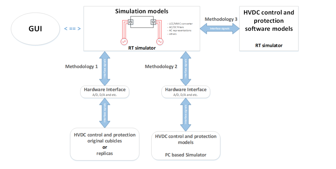
Figure 1 - Concept of RTS environment for HVDC system studies
Real-Time Simulation Modelling for AC Systems
It is impractical and not necessary to model the entire AC systems connected for HVDC simulations, and two types of AC system representations are usually used: a Simplified Static Voltage Source Model and a Dynamic Equivalent Model.
Simplified static voltage source models are used to simulate the infinite bus behind system impedance. Simplified static voltage source models mainly provide the short-circuit impedance and do not necessarily capture the dynamic behavior of the ac network, such as the electro-mechanical transients of machines.
The Dynamic Equivalent Model is generally obtained from full AC system models provided in a transient stability program (RMS). Different AC system load flows are normally considered for the equivalent representations. The level of network details and boundaries in the Dynamic Equivalent Models depend on the study objectives. One of the key features of a Dynamic Equivalent Model is to capture the electro-mechanical machine dynamics, and it should provide system behavior similar to the full ac system models in terms of the following:
- Load flow of key generation, transmission lines and/or interconnection lines
- Short circuit levels of critical buses including converter buses
- Harmonic impedance profiles at the converter buses
- Voltage response to small and large disturbances
- Angular stability/System damping responses
Methodology for Model Validation and Testing
The goal of model validation is to establish a model and its chosen parameters to adequately represent the dynamic performance of the installed devices being modeled for power system studies. This statement, however, leaves significant room for interpretation on the meaning of “adequate” and “power system studies”. Hence, the main goal is to more clearly define these and then present an outline of possible methods for achieving model validation and at what point a model is considered valid for the HVDC system. An overview of possible validation paths is provided in the following figure.
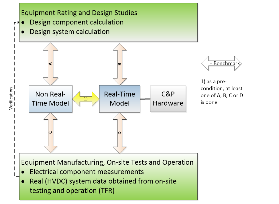
Figure 2 - Validation paths overview
Conclusion
The Brochure provides guidance on RTS modelling for typical HVDC studying scenarios from all aspects of an entire simulation environment. The detailed modelling techniques present in the brochure includes several models with different accuracy for one device or C&P systme, and the guidance for model selection in accordance with different studying purposes as well. A highly extensive reference section and some detailed study examples based on the real HVDC projects around the world are included, signposting all the important relevant publications in the field and providing some practical guidance and reference for RTS application in variety of HVDC studies.

Other Technical Brochures