Recommendations for mechanical testing of submarine cables for dynamic applications
The last years there has been significant development of the floating wind technology and several demonstrators and pilot floating wind farms are now in operation. Several more pilot parks, with increased number of floating turbines and higher total capacity, are currently planned and under development. It is expected that the growth will continue, with full scale floating wind farms being realized during the 2020’s.
Members
Convenor
(SE)
A. TYRBERG
Secretary
(FR)
M. FRANCHET
P. PAN (CN), S. MUELLER-SCHUETZE (DE), O. OTTE (IT), S. KIM (KR), D. ISUS (ES), S. NOBLE (GB), A. PAXTON (GB), A. CHRETIEN (FR), E. CONSONNI (IT), T. YAMAGUCHI (JP), K. OPSTAD (NO), S. INGHAM (GB), M. HART (GB)
CORRESPONDING MEMBERS : C. BONILLA (CA), P. PARADINE (GB)
Introduction
The transition to floating platforms has consequences for several of the involved components, including the submarine cables. The cables that are connected to the floating platforms must be able to withstand the motions induced by the floating device during its service life. This type of cable, that is designed and tested to be able to sustain dynamic loads during its service life, is defined as a dynamic cable.
CIGRE Working Group B1.63 was launched in 2017 with the goal to develop a Technical Brochure providing recommendations for mechanical testing of submarine cables for dynamic applications. The Working Group was initiated to meet the projected growth of the floating wind segment and the need for common and clear guidelines for mechanical tests of dynamic cables for this application. The work was to build on the experience and existing standards from the oil and gas industry, especially ISO 13628-5 [1] and DNVGL-RP-F401 [2], which are related to design, analysis and testing of umbilicals. The work has also taken into account existing CIGRE Technical Brochures, especially CIGRE TB 610 [3], CIGRE TB 623 [4] and CIGRE TB 722 [5], which all include sections related to dynamic cables.
A review of relevant standards and recommendations that can be applicable to subsea cables has first been performed with the aim to identify which of them are also applicable to submarine dynamic cables. The brochure describes the design of the dynamic cable system, including typical cable cross-sections but also ancillary equipment. Technical challenges related to cables for floating wind are also covered. As analysis forms an important part of the design of the dynamic cable system, a dedicated chapter in the brochure describes the type of analysis that are needed and gives recommendations on how to perform them. Finally, the last chapter describes the test sequence for a dynamic cable with a special attention to mechanical tests that are specific to dynamic cables. This includes details and recommendations on the full-scale fatigue test, whose aim is to demonstrate that a cable design can withstand the expected loads during its planned service life.
Survey of existing standards and recommendations
A review of relevant standards and recommendations that can be applicable to subsea cables has been performed. The objective of the survey was to identify which of the existing standards are also applicable to submarine cables for dynamic applications. The review covers IEC (ex: IEC 63026 [6], 60840 [7], 60502-2 [8], 63067 [9] and CIGRE guidelines such as TB 490 [10], TB 610 [3], TB 623 [4], TB 722[5] as well as standards from the Oil and Gas industry, for instance ISO 13 628-5 [1], API 17E [11] and applicable DNVGL standards/recommendations such as DNVGL-RP-F401 [2].
The focus has been on standards related to design, analysis and testing of dynamic cables.
Although several standards and guidelines exist for subsea power cables, none of them covers every aspect of dynamic power cables. The brochure identified aspects that has been considered as lacking in existing standards in relation to dynamic cable design and testing.
Dynamic cable system design
Compared to a static cable, a dynamic cable will be exposed to fatigue loads in the form of reoccurring bending and tension loads and this will influence the design and features of the dynamic cable cross section. In addition, the dynamic cable configuration between the platform and seabed, including ancillary equipment, is also an important part of the system design.
The design of a dynamic cable system is based on the project specific functional requirements and is the result of an iterative process, including thermal/electrical analysis and mechanical analysis.
The design of the configuration is influenced by several factors such as platform offset, avoiding clashing with platform or mooring lines, environmental conditions and cable properties. The most common configurations are:
- Lazy wave configuration, where buoyancy modules are attached to the dynamic cable to create a wave form through the water column,
- Tethered wave configuration, similar to the lazy wave but with a tether connected to the cable close to the touch down point.
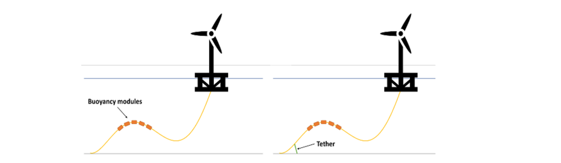
Figure 1 - Illustration of most common configurations, lazy wave (left) and tethered wave (right)
Ancillary equipment is used to achieve the configuration and to protect the cable, such as:
- Hang-off, which is used to provide a fixed connection of the cable to the off-shore structure,
- Bend stiffener, which is used to gradually increase the cable bend stiffness at the interface to the platform,
- Buoyancy attachments, are used to provide uplift to the cable and create the wave configuration,
- Dynamic tether clamp, is used to hold the dynamic cable system in place and consists of a clamp on the cable connected with a tether to a seabed anchor,
- Mechanical protection, are used to protect the cable against for instance abrasive damage at the touch down point.
One important challenge when designing a cable dynamic system is marine growth. Marine biofouling (such as algae or mussels) can accumulate on the cable, especially in sections close to the sea surface. This leads to an increase in the cross-sectional dimensions of the cable and ancillary equipment and an increase in weight. This will impact the results of the dynamic analysis and therefore needs to be considered in the design of the configuration.
Floating wind technical challenges
In comparison to cabling provided for static wind farm applications or dynamic oil and gas applications, the dynamic cabling systems for floating wind turbines faces some new requirements and mechanical challenges.
It is for instance common that floating wind farms employ relatively relaxed mooring systems to reduce structural loads and overall cost, which results in large offsets of the floating structure relative to the water depth. To accommodate these large horizontal offsets, larger and more complex dynamic cable systems and configurations may be required.
Floating wind turbines installed in shallow waters will also face more challenging conditions with regards to seabed stability. The combination of current velocity and wave-induced seawater particle velocity can be significant in shallow waters. More complex seabed stability studies may therefore be necessary including a more detailed understanding of seabed bathymetry and seabed features.
Different options for maintenance of floating wind turbines are currently being studied, where one option is to disconnect the floating wind turbine and tow it back to port and perform the maintenance quayside instead of on-site. This requires the possibility to disconnect the dynamic cable in a controlled manner, wet store the cable during the turbine maintenance period, and the reconnect the dynamic cable when the turbine is back.
Analysis related to dynamic cables
Theoretical analysis for a dynamic cable is typically classified as global analysis or local analysis. The methodology, tools and standards applied for this type of analysis have been developed within the offshore oil and gas industry over many years for flexible products, such as flexible pipes and umbilicals, that are connected to floating oil and gas platforms.
The global analysis is performed to analyse the response and interaction of different components of the dynamic system during various environmental conditions. This includes assessment of loads during extreme weather conditions, assessment of fatigue loads during service life.
The local analysis used to transfer the global loads computed through global analysis into local loads in the different components. This is used to assess the total accumulated fatigue damage experienced by each of these components for the project service life. The local analysis is also used to calculate the mechanical properties of the dynamic cable, such as the bending stiffness. These properties are used as input to the global analysis.
Global and local analysis are typically performed iteratively until a feasible system design has been achieved.
A large set of inputs is required to perform them. This includes environmental data, host/vessel motion characteristics, mooring system details, hang-off position, water depth, cable properties, etc. An overview of the required data is provided in the brochure.
Special purpose tools are required to perform the global and local analysis. The global analysis is performed based on numerical simulations using finite element modelling of the cable. The local analysis can be based on analytical or finite element methods. The fatigue analysis is either performed in standalone tool or a combination of tools enabling to combine the outputs from the global and local analysis.
Typical systems considered in the global analysis includes a cable with a lazy wave (or similar) configuration. Figure 2 gives an example of a global analysis model of a dynamic cable connected to a floating wind turbine.
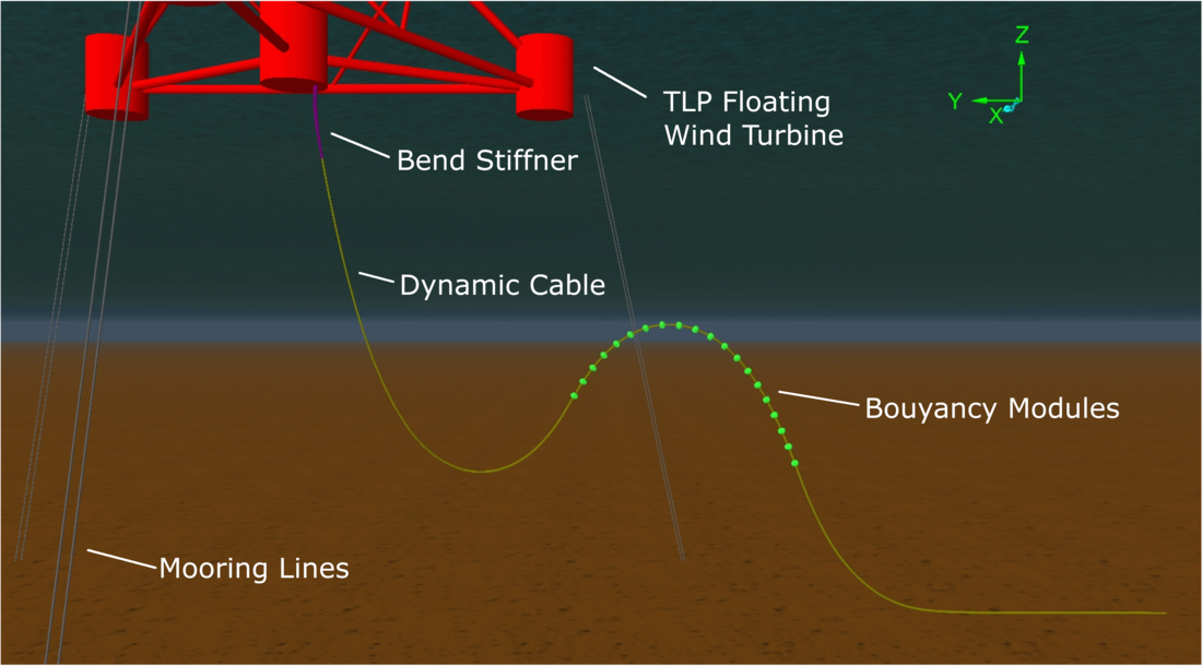
Figure 2 – Overview of the global analysis model used the in fatigue analysis example
The global analysis enables to optimize the cable configuration, identify the required ancillary equipment and to verify the overall feasibility of the cable system. The configuration analysis typically includes the following checks:
- System pliability to accommodate any offsets experienced by the floating platform.
- Static configuration checks: maximum tension and minimum bending radius at nominal position and when extreme platform offsets are applied; adequate seabed clearance; touch-down point position; exit angle at topside. For this both Start of Life (SoL) and End of Life (EoL) conditions are considered, where EoL conditions includes the effect of marine growth and loss of buoyancy in the buoyancy modules over time.
- Dynamic extreme event analysis to ensure that cable tension, compression, bend radius and loads onto ancillary equipment remain within specified limits even for the worst-case scenario, taking into account SoL and EoL conditions.
- Interference analysis to ensure that the cable will not clash with other cables, mooring lines or structures.
- Global fatigue load analysis. For this, the analysis is divided into a large number of load cases representative of the environmental conditions experienced by the cable during service. This results in a fatigue load case matrix based on wave height/period combinations, combined with the environmental directional information. To build this matrix, different methods exist: Rainflow fatigue analysis, Regular wave fatigue analysis, Spectral fatigue analysis.
The results of the global fatigue load analysis are then used as inputs for the local fatigue load analysis in order to convert tension and curvature time series into local stress on the components within the cable cross-section, for each location along the cable. From this result, it is then possible to compute the total accumulated fatigue damage D for the different components. For this, the fatigue life of the components, expressed through a S-N curve (that relates the stress S to a number of cycles to failure N) is required. For each component considered in the analysis, the calculated accumulated fatigue damage over the service life of the cable should be less than:
Where DFF is the design fatigue safety factor. It is applied to cover uncertainties when assessing loads onto structures and for variations in the material properties. It is typically taken equal to 10.
Some important parameters used in the local analysis to extract the relationship between component stress and global loads are the friction coefficients between the layers and components. Friction effects on the helical components result in a stick/slip behaviour during cable bending. They need to be chosen to ensure that they are representative for the expected conditions inside the cable during operation. They can be affected by several parameters such as temperature, wear, contact pressure, etc.
An annex of the brochure provides a detailed step-by-step example of a fatigue analysis for a dynamic cable connected to a floating wind turbine.
Testing of dynamic cables
Dynamic cables can be exposed to a wide range of loading conditions and as such testing is needed to demonstrate that the cable design can withstand the expected loads during the cable’s planned service life. The brochure covers the test sequence for a dynamic cable with a special focus on the mechanical tests that are specific for a dynamic cable. This includes the full-scale fatigue test and additional mechanical tests for characterization of the mechanical properties of the cable and cable components, as well as tests that are related to the loading conditions that can result from dynamic applications, e.g. compression test, clamp squeeze test and clamp slippage test.
The description of the full-scale fatigue test builds on the tests described in TB 623 [4] but with more details provided on the test setup, test considerations and acceptance criteria. Recommendations for the range of type approval of the full-scale fatigue test, both with regards to cable design and application, is also described.
The purpose of the full-scale fatigue test is to verify that the dynamic cable can withstand the expected fatigue loads experienced during service life. For this, different set-ups can be used:
- Tension and angle method, where a tensile force is applied on the cable and a bend stiffener is utilized for curvature control (Figure 3),
- Tension and template method, where a tensile force is applied on the cable and the cable is bent against a template with known curvature (Figure 4).
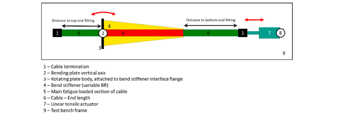
Figure 3 – Tensile and angle flex fatigue test bench scheme
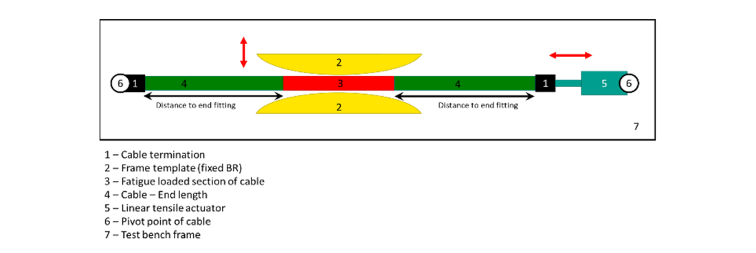
Figure 4 – Tensile and template fatigue test bench scheme
More details on the test setups and the specific considerations are provided in the brochure.
During the full-scale fatigue test, cyclic bending is applied on the cable which is divided into several blocks (at least 5 blocks). Each block is defined by a tensile force, a bending radius and a number of cycles in the block. The total number of cycles from all blocks should be at least 1.5x10⁶. The objective of the block definition is to accelerate the service life regime during laboratory conditions, by means of obtaining a similar distribution of fatigue damage between small and large cycles as experienced during service life. The blocking is defined based on the fatigue analysis results (cf. previous paragraph). It is defined such that the total accumulated fatigue damage experienced during the test is equal or larger than the expected fatigue damage during service life.
During the full-scale fatigue test several parameters are monitored, especially:
- Applied tensile load
- Curvature
- Number of cycles
- Test frequency
- Temperature
At the end of the test, the cable is submitted to an electrical routine test, visual inspection and dissection. Pass/fail criteria as well as further considerations to take into account when carrying out such test are detailed in the brochure.
The full-scale fatigue test is a time-consuming and complex test and it is therefore desirable to define conditions for range of type approval with regards to fatigue loading to avoid having to redo the fatigue test for each project, when the cables are of similar design and the loading conditions are of similar magnitude. The new brochure therefore gives recommendations on when a new full-scale fatigue test or component testing is recommended.
Apart from the full-scale fatigue test, additional mechanical tests are also described in the brochure.
One of the most important characteristics of dynamic cables is their bending stiffness as this will influence the bending response of the cable during dynamic loading. The bend stiffness of a submarine cable is non-linear and can be affected by temperature, bending rate and amplitude. The brochure includes a description of a bend stiffness test where a bend moment is applied onto the cable and the resulting curvature response is measured. The test makes it possible to measure the dynamic bend stiffness and to establish the hysteretic bend moment-curvature relationship.
Component testing is typically also needed, for example to determine the S-N curves of components of the cable (ex: armour wires, conductor strands, screen wires). Component fatigue tests are described in the brochure and reference to relevant test standard is provided. Similar, component tests to characterize the cable with regards to abrasion is also described with reference to existing standards for component testing.
A dynamic cable can be subjected to axial compression, i.e. negative tension, due to dynamic motion of the cable and/or platform. Compressive loads in combination with cyclic bending of the cable has been found to be a mechanism that can trigger lateral buckling of the armour wires. A description of a combined bending and compression test is included in the brochure. The test is performed on a cable sample that undergoes cyclic bending while simultaneously applying a constant compressive force.
Ancillary equipment such as buoys and clamps are clamped to the dynamic cable and held in place by the friction created by the clamping pressure. The clamping pressure must be sufficient to avoid sliding during both installation and extreme conditions during the service life of the cable. Two tests related to clamps are included in the brochure. The first one is the clamp squeeze test, which is performed to verify that the cable can withstand the design clamping pressure and to characterize the cables short and long-term behavior with regards to clamping loads. The second one is the clamp slippage test, which is performed to verify that the clamp will not slip when exposed to the expected maximum tensile load during installation and operation.
Conclusion
Floating wind is expected to grow fast in the future. This technology requires the use of dynamic cables able to withstand the motions induced by the environmental conditions and floating device during its service life. The way this kind of cable is designed and tested is complex and a bit different from what is done for static cables, especially regarding mechanical aspects. It is based on an iterative process, including global and local analysis. In the end, a full-scale fatigue test can be done to validate the design for the specific project. The technical brochure written by WG B1.63 gives details of the different steps of designing a dynamic cable as well as recommendations on how doing the global, local analysis and full-scale fatigue test.
References
- ISO, ISO 13628-5: Design and operation of subsea production systems - Part 5: Subsea Umbilicals, 2009.
- DNVGL, DNVGL-RP-F401: Electrical power cables in subsea applications, 2019.
- CIGRE, TB 610: Offshore Generation Cable Connections, 2015 : https://e-cigre.org/publication/610-offshore-generation-cable-connections
- CIGRE, TB 623: Recommendations for mechanical testing of submarine cables, 2015 : https://e-cigre.org/publication/623-recommendations-for-mechanical-testing-of-submarine-cables
- CIGRE, TB 722: Recommendations for Additional Testing for Submarine Cables from 6kV (Um=7.2 kV) up to 60 kV (Um = 72.5 kV), 2018 : https://e-cigre.org/publication/722-recommendations-for-additional-testing-for-submarine-cables-from-6-kv-um72-kv-up-to-60-kv-um--725-kv
- IEC, IEC 63026: Submarine power cables with extruded insulation and their accessories for rated voltages from 6 kV (Um = 7,2 kV) up to 60 kV (Um = 72,5 kV) – Test methods and requirements, 2019.
- IEC, IEC 60840: Power cables with extruded insulation and their accessories for rated voltages above 30 kV (Um = 36 kV) up to 150 kV (Um = 170 kV) – Test methods and requirements, 2020.
- IEC, IEC 60502-2: Power cables with extruded insulation and their accessories for rated voltages from 1 kV (Um = 1,2 kV) up to 30 kV (Um = 36 kV)- Part 2: Cables for rated voltages from 6 kV (Um = 7,2 kV) up to 30 kV (Um = 36 kV), 2014.
- IEC, IEC 63067: Power cables with extruded insulation and their accessories for rated voltage above 150 kV (Um=170 kV) up to 500 kV (Um=550 kV) - Test methods and requirements, 2011.
- CIGRE, TB 490: Recommendations for Testing of Long AC Submarine Cables with Extruded Insulation for System Voltage above 30 (36) to 500 (550) kV, 2012 : https://e-cigre.org/publication/490-recommendations-for-testing-of-long-ac-submarine-cables-with-extruded-insulation-for-system-voltage-above-30-36-to-500-550-kv-this-tb-replaces-electra-article-elt1891
- API, API 17E: Specification for Subsea Umbilicals, 2017.

Other Technical Brochures