Improvements to PD measurements for factory and site acceptance tests of power transformers
The Technical Brochure (TB) of Joint Working Group JWG A2/D1.51 deals with possible improvements to partial discharge (PD) measurements for factory acceptance test (FAT) and site acceptance tests (SAT) of power transformers. In the joint working group, it is common understanding that a sensitive PD measurement is in the best interest of both, the transformer manufacturer, and the end user of power transformers. It ensures high quality, reduces the probability of failure and consequently lowers operational costs during the technical lifetime of transformers.
Members
Convenor
(DE)
S. COENEN
Secretary
(DE)
S. MARKALOUS
T. LINN (CH), P. MRAZ (CH), M. BELTLE (DE), A. NADERIAN (CA), R. CSELKÓ (HU), V. SCHMIDT (DE), P. FEHLMANN (CH), R. SCHWARZ (AT), J. FUHR † (CH), M. SIEGEL (DE), R. GATECHOMPOL (TH), M. SÖLLER (DE), M. HÄSSIG (CH), J. SZCZECHOWSKI (US), S. HOEK (DE), D. TABAKOVIC (US), M. JUDD (GB), S. TENBOHLEN (DE), U. KEMPF (DE), M. WEBER (DE)
With that regard, it is neither the intention of this brochure to change acceptance criteria allowing easier passing of FAT/SAT, nor to tighten the acceptance criteria by introducing an additional measurement method measuring signals without a clear indication of critical PD activity. Rather, it is the aim to provide a guide that sensitises the users for dos and don’ts for electrical PD measurements. The advantages of UHF measurements for SAT and FAT are explained and how the necessary reproducibility of the method can be achieved with the help of a suitable calibration of the measurement setup.
UHF PD measurements themselves need to be reliable and reproducible to become a reliable and easily accessible indicator for transformer’s quality useable in both, FAT and SAT. Therefore, topics addressed in the brochure regarding UHF PD measurements include: the calibration of both, used sensors and the measurement recorders; system sensitivity regarding real PD defects in a transformer; robustness against noise; number of and placement of sensors at large power transformers; procedures for acceptance tests in the factory and on-site.
The objective of any calibration is to ensure a general comparability and reproducibility of measurements independent of used devices and setup conditions. It must be noted that the UHF calibration should not be misinterpreted as an attempt to correlate the readings of the UHF method (calibrated measurements in V/m) with the electrical method according to IEC 60270 [1] in terms of pico-Coulomb (pC).
Furthermore, the TB provides additional basic information for a deeper understanding of PD measuring by reviewing the conventional electrical method according to IEC 60270 and comparing it to the UHF method to illustrate their differences. To get the best usage for both, FAT and SAT, the brochure discusses and evaluates given and alternative methods and concludes with recommendations for individual improvements.
Electrical Method According IEC 60270 and Its Calibration
PD measurement performed according to IEC 60270 [1] has become an essential tool for a product’s quality assurance. The main goal of IEC 60270 is to standardize and unify PD measurement to get comparable results for tests performed at various locations, with different equipment and by different operators. To achieve this goal IEC 60270 has defined a complex set of processes and key parameters, which are essential to be followed carefully. The original IEC 270 standard (1980’s) is designed for testing lumped capacitive test objects. Nevertheless, from long-term experience, it has been found that good and plausible results can be obtained for test objects with windings such as transformers and electrical machines as well. However, especially in case of testing more complex RLC systems, certain rules need to be followed and particular limitations should be considered.
The purpose of the TB is to provide clear and unambiguous guidelines on how to perform repeatable, plausible and comparable PD measurement according to the IEC 60270.
Electromagnetic Method (UHF) and Its Calibration
PD related radiation of electromagnetic (EM) waves was first investigated and used as a PD detection method on gas insulated switchgear in the late 1980s. EM radiation of PD sources was also found for PD under oil within power transformers [2], [3]. The principle of the method is expressed exemplary for a power transformer in Figure 1.
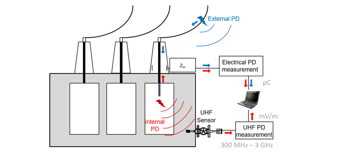
Figure 1 - Principal of electrical and UHF PD Measurements in power transformers [4] with signal paths: electrical galvanically coupled measurement and electromagnetic radiation of PD
At the beginning of this Joined Working Group, UHF PD measurements were not well defined. There were mostly non-characterized sensor types of different manufacturers at hand. Also, there were different non-comparable installations into the transformer. Yet, practical cases have proven over several years, that UHF PD impulses can be measured with e.g. an oscilloscope or an spectrum analyser and the method has been shown to be sensitive. Unfortunately, comparable measurements across setups using different sensors or measurement devices were not possible because a general method for system comparison was not available.
To solve lacking measurement system comparability, UHF measurement systems require a calibration including a validation of the UHF sensor sensitivity. The TB has the intention to propose such a calibration procedure to allow reproducible and comparable UHF measurements independently from model and make of used measuring equipment including measurement cables, accessories and sensors.
UHF sensors and their sensitivity
Two different methods are commonly used for installing UHF Sensors on transformers. Early available UHF sensors types are installed using oil drain valves, which are increasingly fitted to new transformers specifically for condition monitoring purposes [5]. For the second method, a mounting hole is prepared either on the main tank or a removable hatch cover plate and a robust dielectric window is attached to it to maintain the oil seal. A planar antenna can be mounted on this dielectric window or, in more advanced implementations, the window can take the form of a “pocket” for mounting the sensor through the hole inside the transformer’s Faraday cage for higher sensitivity [6]. The need for holes in the tank introduces limitations to the implementation of this method for transformer in service but may be well established during manufacturing for new transformers for FAT/SAT applications. For new transformers, it is advised to install four window UHF sensors directly, because they are easier to use (fixed insertion depth, no moving parts, installation without oil handling, low in cost) and provide a higher sensitivity (better earthing, lower disturbances measurable, flat frequency response).
During the practical tests and discussions throughout the duration of the working group, a reduced frequency range has been established for transformer applications. Instead of the full UHF range defined up to 3 GHz, a frequency range between 300 MHz and 750 MHz appears sufficient to detect PD under oil. The sensors which can be used for improved FAT and SAT should have attached a documentation of the frequency response. The TB explains in detail how to achieve the frequency response of UHF sensors.
Calibration of the UHF Method
There are two main factors that must be addressed by UHF calibration. The particular measurement device including accessories such as cables, filters, attenuators, pre-amplifiers, etc. is addressed in the first step of the calibration by introducing the calibration factor KM, see section 3.2.1. The influence of the UHF sensor, essentially its sensitivity and its conversion from an electric field strength to a voltage signal, is included using calibration factor KS, see section 3.2.3. Using the proposed UHF calibration method, different UHF measurement systems (including UHF sensors, cables, amplifiers, attenuators, filters, and measuring devices) become comparable when used at the same measurement position.
Calibration Method for the Measurement Devices: KM-Factor
The measurement setup consisting of the recorder and connected cables, pre-amplifiers and other accessories is exposed with a defined calibration impulse, see Figure 2.
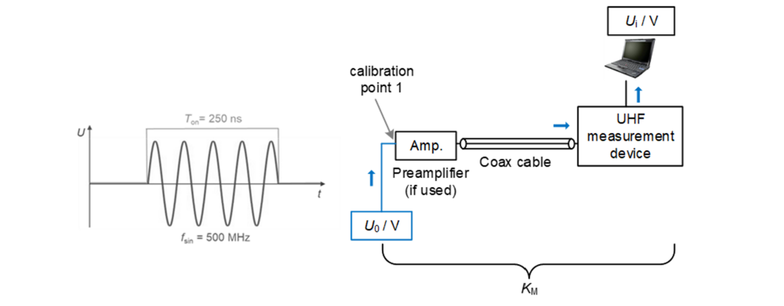
Figure 2 - Calibration Setup: measurement device & cables to derive KM factor [7]
This type of waveform is called pulse modulated RF (PuM RF). It is defined as a sinusoidal signal with fsin = 500 MHz and a duration of Ton = 250 ns repeated two times per phase period (meaning 100 times per sec for 50 Hz systems). A minimum time Ton allows the input state of UHF measurement devices to tune on the correct signal amplitude. The signal is injected directly into the connector between antenna and cable/pre-amplifier without the antenna being attached, see Figure 3‑2. Hence, all effects of cables and accessories are included into the signal path: the measurement device will detect a specific signal Um as a result of the defined calibration impulse (system filter response).
Hence, the resulting calibration factor KM can be calculated from the ratio of both values:
Uo ... sinusoidal reference amplitude
Um ... voltage reading provided by device
By introducing the KM calibration factor, comparability between different measurement devices using arbitrary cables and accessories can be achieved. The point of calibration is represented by the connection between cable connector and the UHF sensor. Compared to narrowband calibrations in frequency domain like they are performed e.g. for EMC test setups, the presented time domain approach represents a simplified method with a reduced accuracy. In order to keep the method simple for practical SAT and FAT applications, the method has been shown to be robust in laboratory tests none the less.
Because KM incorporates only the measurement system, it is independent of any transformer it is applied to.
Calibration Method for the UHF Sensor: KS-Factor
In order to include the sensor’s characteristic into the calibrated path, its antenna factor AF(f) is required. The AF describes the conversion between the applied electric field strength at an UHF sensor and the resulting output voltage of an UHF sensor. Due to its definition, a low AF yields a high antenna sensitivity:
U(f) … voltage at the sensor (antenna) terminals
E(f) … electrical field strength at the sensor of the incident electromagnetic wave generated by PD
For drain valve UHF sensors, the actual insertion depth must be the same both during AF determination and UHF PD measurement in the transformer. Highest sensitivity for drain valve UHF sensors is achieved usually reached at insertion depth of minimum d = 50 mm for most sensors, which is recommended to use for calibrated UHF measurements. Window type UHF sensors use an optimized fixed insertion depth.
The known transfer function provided by the AF(f) allows to incorporate the sensors sensitivity into the calibration. This is shifting the calibration point from the cable end (see chapter 3.2.1) to the sensor tip inside the transformer. Hence, the AF(f) needs to be specified for every UHF sensor type individually. Therefore, a “calibration sheet” or “routine test report” including the sensor’s AF(f) from the manufacturer is considered a precondition for UHF calibration. A UHF sensor without known AF(f) cannot be used for calibrated electromagnetic PD measurements. The commonly used UHF sensor types (drain valve and window type) consisting of a monopole antenna provide the highest sensitivity in the frequency range of 300 MHz up to 750 MHz, where the AF(f) is lowest.
Simplification of AF
To simplify the calibration procedure for time-domain broadband measurement systems, the frequency dependent AF(f) is reduced to a constant calibration factor KS, which is valid with sufficient accuracy for the most used UHF PD frequency ranges. It is proposed to calculate the constant factor as the mean value of AF(f) from 300 MHz to 750 MHz. AF(f) characterisation is performed inside the standardized setup of a GTEM cell. This can be done either in air, where the actual AF(f) has to be recalculated by including the relative permittivity of transformer oil, or directly in an oil-filled GTEM setup. The mean value in the corresponding frequency range is calculated, which yields calibration factor KS.
Figure 3 shows a general example of the correlation between frequency dependent AF(f) and the calculated simplified antenna factor AFs = KS.
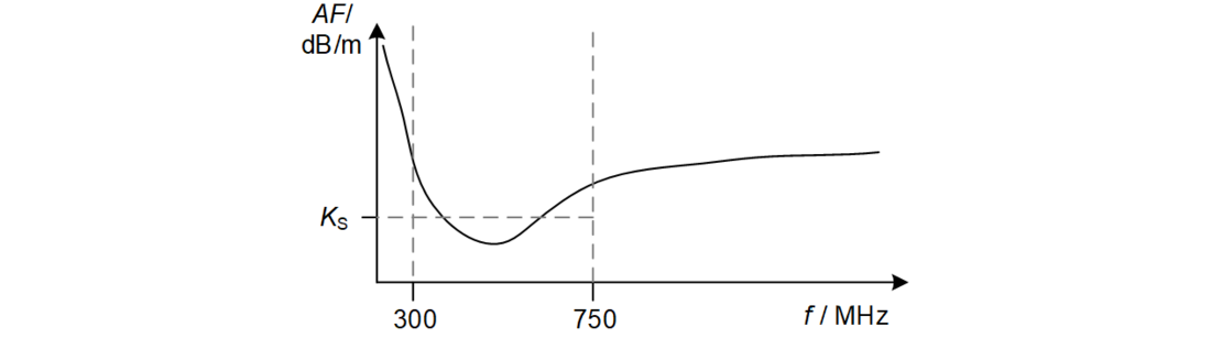
Figure 3 Example of simplifying the AF to derive KS [7]
As already discussed in the previous section, this step represents a significant simplification compared to narrowband, frequency dependent conversion but provides sufficient accuracy for time domain SAT / FAT UHF PD measurements. Therefore, it must be noted, that the proposed KS calculation is only valid for broadband UHF measurement systems. For narrowband measurement systems, the actual linear AFlin at the centre frequency AFlin (fcenter) should be used for KS.
Using KS of the sensor, the new calibration point is shifted inside the transformer to the UHF antenna, see Figure 4.
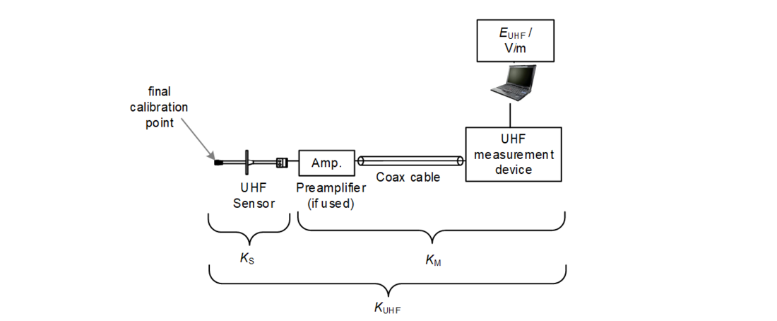
Figure 4 Calibrated measuring point at the UHF Sensor – independent from transformer [7]
Hence, the entire signal path from sensor to measurement device is calibrated and can therefore yield comparable values of electric field strength at the sensor measured in V /m.
Calibration Procedure of the entire UHF Measurement System: KUHF-Factor
The complete UHF calibration factor KUHF is calculated by:
Using KUHF, an impulse Ui measured with the UHF measurement system can be recalculated and results in a value correlated to the incident electrical field strength at the UHF sensor.
This value is named “measured UHF electrical field strength” EUHF and is measured in V/m.
Because this procedure incorporates the measurement system only, it is independent of any transformer it is applied to. Hence, a recalibration is not required if the device under test (the transformer) changes. It is sufficient only to calibrate a dedicated measurement system (recorder and cable setup) in standard intervals.
The comparability to other calibrated systems would be maintained for any installation on different transformers, if no components of the dedicated system are changed (e.g., cables, etc.). This is only valid if the direct surroundings of the sensor in the tank do not change significantly.
As the structure inside the specific transformer cannot be considered when KS is determined in a GTEM cell setup, KS only represents an approximation. Because these structures are part of the individual device under test (the transformer) and not of the measurement setup, it cannot be included in a calibration procedure of the measurement setup. Figure 5 shows the measurement setup at a power transformer with UHF sensor installed at a drain valve.
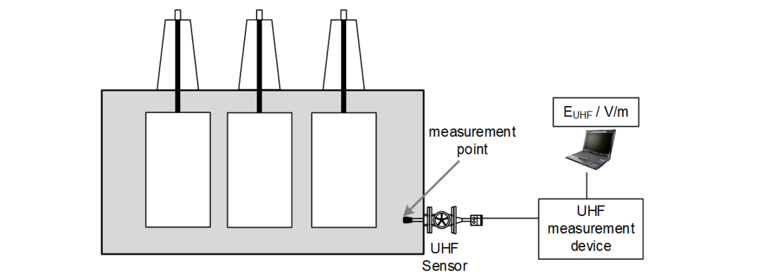
Figure 5 UHF Measurement setup at a transformer [4]
It has to be noted, that a performance check (explained in TB) is additionally recommended to demonstrate the functionality of the measurement chain including a transformer on a case-by-case base.
Recommendation for Improved PD Acceptance Tests
The main improvement for FAT and SAT provided by the TB is the possible achievement of general comparability of PD measurements in the UHF range. This provides benefits for both transformer manufacturers and utilities.
In order to achieve comparability of FAT or SAT tests for UHF PD measurements, some requirements have to be met. The used measurement system must be calibrated, so all influences originated form the measurement system and sensor can be eliminated.
To achieve comparability between UHF PD measurement systems, this TB proposes a UHF calibration procedure, which requires the use of UHF sensors with a known antenna characteristic (calibrated sensitivity). The characteristics can be provided either by the antenna factor AF or in a simplified, more practical approach for time-domain impulse measurements proposed in this brochure by the KS factor of the sensor. The influences of the measurement system can be calibrated with the introduced factor KM. A measuring system should be able to incorporate the calibration factors KS and KM in its signal processing software.
It is recommended to use predominantly permanently installed UHF sensors (such as the window type) for new transformers, because they are easier to use (insertion depth does not have to be set correctly) and provide usually higher sensitivity (a better AF) and better (flat) frequency response. To provide high coverage for PDs within the entire power transformer, in the TB four UHF sensors are recommended as standard configuration. At least two sensors should be used at absolute minimum to enable a performance check. As high-end configuration six or eight sensors can be used, depending on sensitivity requirements and tank size.
In general, documentation remains a very important factor to assure the comparability of measurements, especially for comparisons between FAT and SAT measurements (e.g. before and after transportation and onsite commissioning of a transformer). Relevant points to be documented are listed in the TB. Regarding IEC, documentation should e.g. include a description of the setup, the capacity of the coupling capacitor, the PD calibration level applied (e.g. 100 pC), recorded noise levels after calibration, the frequency range used, and details of the measurement instrument.
Concerning conventional measurements according to IEC 60270, a calibration method has been established for many years, meaning the basic requirement for comparability is already met. In relation to larger test objects and/or test objects with windings, such as power transformers, electrical PD measurements are recommended in the lower frequency range (upper cut-off frequency typically 200 to 300 kHz) for FAT scenarios. The low-frequency range of PD signals experiences the lowest attenuation and hence provides the highest sensitivity for PD signals throughout the transformer. However, such settings might lead to noisier PD measurements under SAT conditions. Examples given in the TB show that the apparent charge value can differ significantly dependent on the PD location, even when measuring in a frequency range according to IEC 60270. Measuring at frequency ranges outside the IEC spectrum or using narrow-band measurements carries risks of greater error and defeats the purpose of standardization. Regarding these facts, it is questionable whether a pass/fail decision for FAT and SAT that relies solely on measuring the apparent charge level as acceptance criteria can provide the optimum quality assurance.
If possible, PD measurements at FAT and SAT should be performed using both measurement principles electrical according to IEC and UHF method as explained in the TB. Hence, the overall sensitivity to detect PD is the highest and the usage of different physical propagation mechanisms provides the option to validate and confirm single measurements. In most cases, UHF PD measurements are easier to perform at SAT compared to IEC measurements. Therefore, a PD measurement validated using both methods at FAT could be confirmed at SAT using at least one method.
FAT and SAT require an acceptance criteria or threshold value acting as “pass/fail” criteria. Due to several reasons highlighted in the TB, the only focus of the apparent charge is not meaningful. It is the common understanding of the members, that as state of today, recommendations regarding acceptance thresholds for pass/fail criteria for UHF measurements are not feasible. Furthermore, there is no general correlation in terms of a certain ration between electrical and UHF measurements for power transformers.
Measurement Campaigns and Outlook
In several measurement campaigns, the validity and feasibility of the proposed calibration method has been demonstrated in a laboratory setup by using different UHF PD measurement devices from several manufacturers. The tests revealed a total measuring inaccuracy after calibration of only about 10% across 4 different UHF measurement systems in a setup with an artificial, stable PD signal. In a second approach, the same laboratory setup was used with two real PD sources at applied high voltage. With 5 different UHF measurement devices and 2 different UHF sensors, the calibration proposal was evaluated, see the results in the TB.
As with the electrical PD measurement method, an algorithm similar to that described in IEC 60270 to display the “largest repeatedly-occurring UHF PD magnitude (EUHF in V/m)” is proposed. Additionally, manufacturers need to incorporate the facility to perform KM and KS calibration into their software and rescale readings accordingly to the “measured UHF electrical field strength” EUHF in V/m.
With UHF measurement systems that have incorporated both, the proposed UHF calibration procedure and the automatic output of the “largest repeatedly occurring (UHF) PD magnitude”, a measurement campaign similar to the presented laboratory test needs to be performed in the future: Using calibrated systems, the transformer community can gain experiences with UHF PD measurements in FAT and SAT (and in continuous PD monitoring) and may identify criteria for UHF PD testing. After collecting UHF PD measurement results with calibrated UHF measuring systems, a future working group may develop rules for threshold values or other acceptance criteria for UHF. Research teams around the globe are asked to perform calibrated UHF measurements as well to collect as much comparable practical experience as possible with the proposed calibrated UHF technique.
References
- International Electrotechnical Commission, IEC 60270: High Voltage Test Techniques - Partial Discharge Measurements, Geneva, Switzerland: IEC, 2000.
- S. Coenen, Measurements of Partial Discharges in Power Transformers using Electromagnetic Signals, Germany: BoD - Books on Demand, Norderstedt, , ISBN 978-3-84821-936-0, 2012.
- S. M. Markalous, Detection and Location of Partial Discharges in Power Transformers using acoustic and electromagnetic signals, Sierke Verlag, Göttingen, ISBN 9783933893970 , 2006.
- S. Coenen, M. Siegel, M. Beltle, S. Tenbohlen, S. Hoek, P. Fehlmann, R. Schwarz, T. Linn, U. Kempf, M. Weber und J. Fuhr, D1-116: Proposal of a Calibration Methodology of UHF Partial Discharge Measurements for Power Transformers,“ in CIGRE Session 48, Paris, 2020: https://e-cigre.org/publication/SESSION2020_D1-116
- CIGRE Technical Brochure 343, Recommendations for condition monitoring and condition assessment facilities for transformers, Paris: CIGRE WG A2.27, 2008: https://e-cigre.org/publication/343-recommendations-for-condition-monitoring-and-condition-assessment-facilities-for-transformers
- CIGRE Technical Brochure 662, Guidelines for partial discharge detection using conventional (IEC 60270) and unconventional methods, Paris: CIGRE WG D1.37, 2016: https://e-cigre.org/publication/662-guidelines-for-partial-discharge-detection-using-conventional-iec-60270-and-unconventional-methods
- M. Siegel, Calibration Methods for Reproducible and Comparable Electromagnetic Partial Discharge Measurements in Power Transformers, Stuttgart, Germany: BoD - Books on Demand, Norderstedt, ISBN 9783752628180, 2020.

Other Technical Brochures