DC grid benchmark models for system studies
HVDC technology is an increasingly important power system technology and the concept of HVDC grids has evolved rapidly, receiving increasing attention internationally. As more complex, multi-terminal systems are being built and planned, and even more complex grid systems are in discussion. To help achieve generally accepted standards, aid equipment interoperability, and support R&D in this important and emerging field, a common set of HVDC grid benchmark models to allow communication, standardization and training is required to achieve collaboration in research and comparison of results. This Technical Brochure has developed, and provides benchmark models of seven candidate multi-terminal HVDC grids/systems. Reviews of the built and planned HVDC systems around the globe, and R&D literature, underpins the selection of these models. The models are described, sample results are provided, and the files for the benchmark models are given in a variety of offline and RT simulation packages/platforms.
Convenor
(CN)
T. AN
Secretary
(CA)
R. AZAR
Secretary
(CA)
M. EL-CHEHALY
M. BARNES (UK), S. AZAD (CA), J. JARDINI (BR), S. ELIMBAN (CA), H. YE (CN), C. D. HAN (CN), J. SERRANO (ES), A. MORALES (ES), S. DENNETIERE (FR), W. X. LI (CA), S. SANTO (BR), T. DOBBIN (BR), W. LIN (CN), H. SAAD (FR), J. LIANG (UK), R. T. PINTO (DE), M. OHRSTROM (SE), I. BELANGER (CA), H. DING (CA), P. YANG (CN)
Corresponding Members: R. FERRER SAN JOSÉ (ES), C. MUSSI (IT), B. SILVA (PT), E. GALVAN (ES), M. SZECHTMAN (BR), Z. Y. HE (CN), J. AWODOLA (GB), J. Z. XU (CN)
Introduction
HVDC Grids are today considered to be the most effective and promising technical solution for the connection of renewable onshore and offshore wind generation, remote energy resources, ocean power supply, sharing of energy storage including hydro plants, as well as interconnection of AC systems perhaps even on a global scale.
The concept of HVDC Grids accordingly is evolving rapidly, Nan’ao, Zhoushan and Zhangbei are good examples of multi-terminal systems/grid in China. The Luxi back-to-back system and the Skagerrak 3 and 4 mixed VSC-LCC bipole demonstrate how LCC and VSC systems may be combined. For their continued development, the use of common benchmark models, with publicly available baseline study results, is extremely important, essential and necessary. This allows collaboration in research, comparison of results directly and effectively, and ultimately the formulation of common standards of DC grid equipment and operating standards. It allows the rapid training of engineers with public models that have been checked by a wide group of engineers. It also serves as a useful tool for the development of modelling of new control systems.
Existing HVDC benchmark models have largely been point-to-point, with the notable exception of the HVDC grid test system produced by Cigre WGs B4-57, published in Technical Brochure 604, which has been widely used. This multi-terminal test system was largely created at a time when rapid development of offshore wind in Europe meant that multi-terminal VSC-HVDC was becoming an important topic, and the HVDC grid test system reflected this. Since then a number of other topics have emerged, such as collection, integration and transmissions of onshore renewable power generation over long distances, integration of the previous LCC point-to-point systems to form LCC-HVDC grids, the development of mixed LCC-VSC hybrid HVDC grids, AC system interconnections via DC grids, etc.
The required modelling is discussed and various of ‘benchmark’ models are proposed in this brochure. The models have been modelled in a number of offline and real time (RT) simulation packages and example results are illustrated in the brochure. Full models are also available online. While it is not the intention of this brochure to offer models for every possible case, there are sufficient variations to serve as starting points for many common configurations under investigation at present.
Scope
The scope of work for the Working Group was to establish HVDC grid benchmark models to cover most of the different HVDC grid applications for different types of studies. This was based on the output of WGs B4-52, B4-57, B4- 58 and B4-59, and the test models developed and published by Global Energy Interconnection Research Institute (GEIRI). Both VSC and LCC HVDC grids were to be considered, and the possibility and limitations for LCC HVDC grid were to be addressed.
Methodology
The Working Group examined the various worldwide applications of LCC-based and VSC-based HVDC technologies, with the objectives of providing several HVDC grid models for most applications of DC grids. To do so, the following activities were performed by the Working Group:
- A global survey was conducted, the goal of this was to outline the background context in the wider framework of electricity systems; the basic information of existing HVDC systems; the potential applications of DC grids in most continents. It also intended to summarize the documented proposed configurations and topologies of HVDC grids for regional, long distance and other HVDC grid applications.
- A literature review of the existing HVDC grid models proposed by researchers for different types of studies and for different HVDC grid applications. as well as various small-scale laboratory demonstrations of multi-terminal HVDC systems that are available around the world was undertaken. This was based on the review of the HVDC grid related papers published mainly in IEEE transaction journals, IET journals, ELSEVIER journals and Cigre conference proceedings between 2012 and 2018.
- Based on the outcomes of the above two activities, seven HVDC grid benchmark models (six new and one existing Cigre B4 HVDC grid test system) were developed to provide unified study platforms to meet the needs for most different HVDC grid studies and applications.
- The modelling methodology and models of the key components (i.e. AC/DC converters, DC/DC converters, DC circuits breakers, renewable generation, and conventional AC equipment) of the benchmarks for load flow (LF) and electromagnetic transient (EMT) studies are introduced.
- The offline modelling and verification of all seven benchmark models was undertaken by building their LF and EMT types of models with different types of software (i.e. MATLAB, DigSilent, PSCAD and/or EMTP) and the corresponding dynamic simulation results of two dynamic disturbances were conducted.
- Finally, the general details of models used to achieve real time simulation were provided followed by the real time EMT simulation models for BM1 to BM7 (excluding BM6) built on RTDS NovaCor simulator (BM1 to BM4) and Hypersim (BM1 to BM7 excluding BM6), and verified by two dynamic simulations.
Survey and literature review
As a first step, a survey of global HVDC installations was conducted to assess the existing, planned and proposed (potential) HVDC schemes around the globe, along with their configurations and applications. The global survey revealed that DC grids could potentially be formed in any continent, especially in Asia, northern Europe and North America, due to the growing penetration and integration of renewables, as well as the increasing necessity of power exchange between neighbouring networks and high-power transmission over long distances. It also identified the presence of multi-terminal HVDC systems that are currently operating or in planning in China, USA and Europe.
Potential DC grids are expected to be developed gradually from small scale multi-terminal systems, of three to five terminals, towards larger scale grids with more terminals. Such grids will comprise both underground/undersea and overhead lines with different configurations and voltage levels. Thus, appropriate modelling of different potential configurations is particularly important because there is unlikely to be a single formal ‘system architect’ of the whole eventual grid. For each region, the potential applications of DC grids were compiled as well as the characteristic requirements for modelling these applications. This was followed by a literature review of existing DC grid models and their applications, as well as of laboratory hardware test-systems around the globe.
The literature review examines the existing HVDC test system from Cigre B4 and GEIRI models and their applications, the most common DC grid models used by researchers for different types of studies and for different DC grid applications, as well as various small-scale laboratory demonstrators of multi-terminal HVDC systems that are available around the world. This demonstrated that a set of benchmark systems will be required to facilitate comparison of results from various DC grid related studies – the range of applications means that a ‘one-size-fits-all’ approach would be insufficient. The applications of the Benchmark models (BMs) should include, but are not limited to the following:
- Offshore/onshore renewable integration;
- Feasibility study of Multi-Terminal DC (MTDC) network;
- Interconnection of DC grids with different voltage levels;
- Key DC equipment and components;
- Load flow and electromagnetic transient (EMT) studies;
- Protection and control;
- Dynamic performance analysis and control;
- Real time simulation of multi-terminal DC systems.
HVDC Grid benchmark models developed
The Technical Brochure has developed Seven (7) BMs as summarized below.
BM1 - HVDC grid model for the integration of large scale onshore renewable generation
This model represents a ±500 kV Voltage Source Converter (VSC) HVDC grid for the integration of large scale onshore renewable generation. A number of countries including the USA, China and Australia are actively studying the widespread roll-out of largescale onshore renewables, and HVDC transmission becomes economically attractive at distances of several hundred kilometers.
The literature review carried out in the Technical Brochure indicated that the most common DC grid models used for the EMT studies are of three to five DC terminals with one mesh and one voltage level. Thus, the model is designed for one DC mesh formed by the minimum three DC buses, but with additional DC terminals and including major different types of largescale renewables (i.e. wind, solar and hydro) connected to the DC grid (Figure 1).
The model has also two AC/DC hybrid meshes and this, together with the DC mesh, is able to provide redundancies to the system. As it has different types of renewables connected together, generation has temporal and spatial complementarities that are useful in balancing the power flow, increasing the availability and reliability of the system. Moreover, the reason why the DC grid is connected to two AC systems (750 kV and 220 kV) is to increase the flexibility of the integration of a local VSC DC grid to increase the practicability of the model.
The model is suitable for (but not limited to) feasibility studies of HVDC grids for integration of renewables; EMT studies with the converters modelled in detail for designing and verifying the control functions of HVDC grids; impact studies of AC system strength.
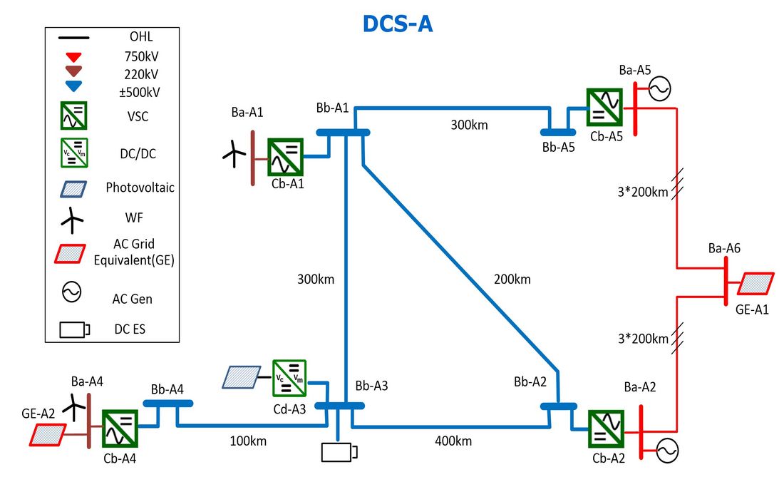
Figure 1 - BM1 - HVDC grid for integration of large scale onshore renewable generation
BM2 - ±800 kV Line Commutated Converter (LCC) HVDC grid model
This system is formed by interconnecting two existing point-to-point LCC-HVDC schemes. The interconnection of the two schemes is achieved by installing two DC lines at the both ends on the DC links, highlighted as dashed lines on Figure 2. If the power flow is kept in one direction (e.g. from left to right) the requirement of DC voltage reversal can be avoided. A number of countries have LCC systems connected in close proximity, not least China, and the need to study converter interactions or the interconnection of links is pressing.
This model is suitable for (but not limited to) carrying out LCC-HVDC grid feasibility studies and studies on the different converter control schemes.
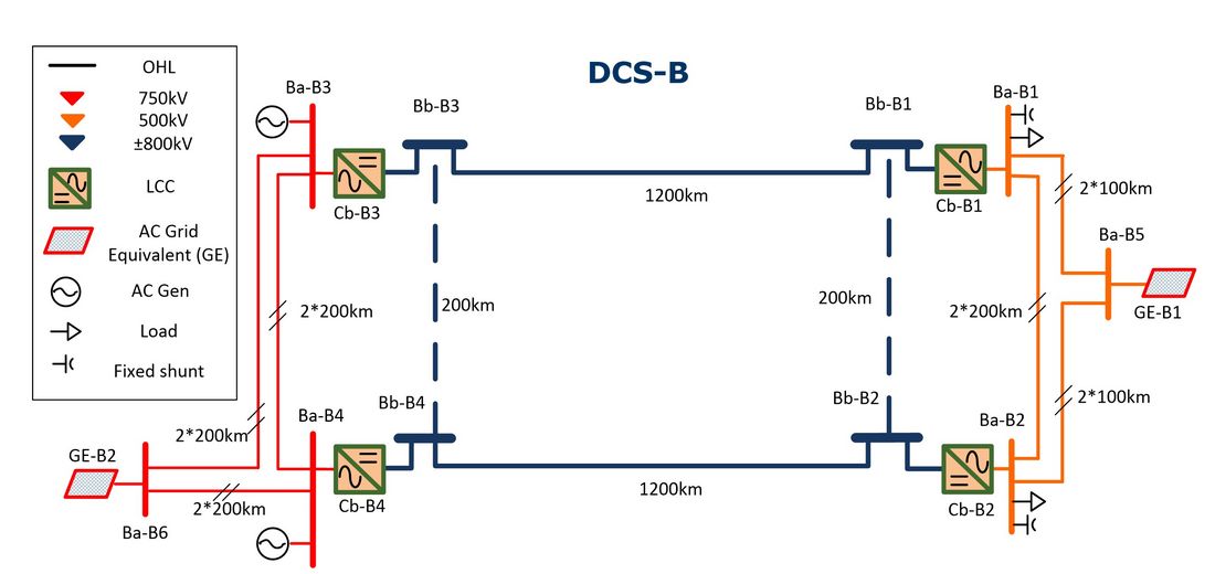
Figure 2 - BM2 – LCC-HVDC Grid
BM3 – MTDC system model for integration of small onshore renewables
This model is complementary to BM1 and models a smaller-scale integration of onshore renewables with a ±320 kV system. It is suitable for (but not limited to) the same studies as listed for BM1 above. The model has an AC/DC hybrid mesh only to provide redundancy to the system – in contrast to BM1’s DC plus AC/DC mesh (Figure 3).
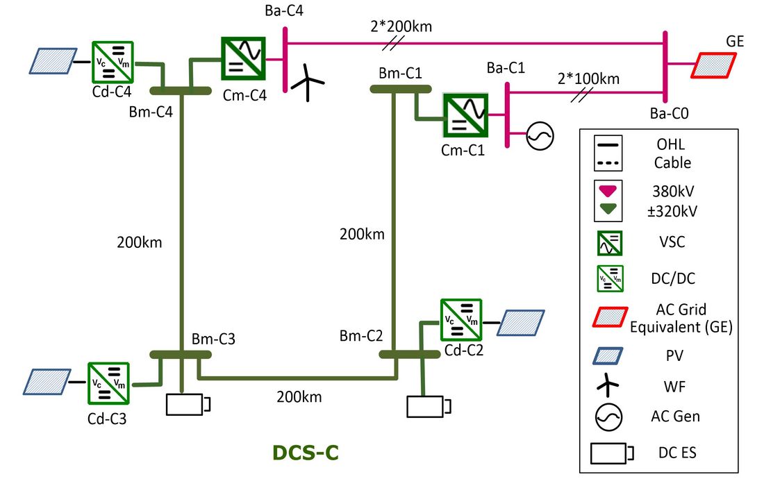
Figure 3 - BM3–MTDC system for integration of smaller scale onshore renewable generation
BM4 - HVDC grid model for offshore wind power and offshore oil/gas platform connection
Offshore wind power integration using HVDC is well-establish in Germany and is being planned elsewhere in Europe. This model was first developed by Cigre Working Groups B4-57 and B4-58, and is already widely used. It covers a point-to-point HVDC link, a multi-terminal HVDC system and a meshed HVDC grid. It has two voltage levels and two DC/DC converters (one for different voltage level interconnection and the other for power flow control only) (Figure 4).
Some potential for interactions of different lines types (i.e. overhead line and cable) has been considered in the BM by connecting overhead lines and cables in series. It is suitable for (but not limited to) for electromagnetic transient (EMT) and electromechanical transient (i.e. RMS dynamic) studies; offshore HVDC grid studies; design and verification of offshore HVDC grid system coordination control functions.
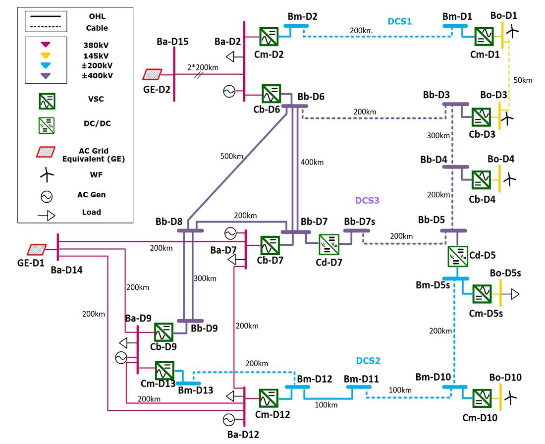
Figure 4 – BM4 –HVDC grid for offshore system integration wind generation and offshore platform loads
BM5 - LCC/VSC hybrid HVDC grid model
This system is made of two interconnected small-scale models (BM1 and BM2), for the integration and transmission of renewables. If the LCC terminals are replaced by VSC terminals, BM5 is also a medium sized VSC HVDC system set for integration of local renewables and transmission of surplus power to a faraway load centre over long distances. The two HVDC systems (rated ±800 kV and ±500 kV) link two asynchronous networks. The model is suitable for (but not limited to) EMT and RMS studies; feasibility studies for VSC/LCC hybrid HVDC grids; studies on different converter control schemes; assessment of the transient performance of LCC/VSC hybrid systems.
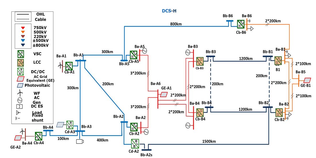
Figure 5 - BM5 - Medium-sized LCC-VSC hybrid HVDC grid model
BM6 - HVDC grid model for parallel interconnection of two AC power systems
The BM6 system considers AC two systems interconnected by a multi-terminal grid in parallel with and HVDC point-to-point system (Figure 6).
The DC grid in the middle is of 10 AC/DC converters, three DC/DC converters to interconnect three different DC voltage levels (±400 kV, ±500 kV and ±800 kV). A parallel top route is formed by three buses and is independent from the other routes. The DC grid is formed by three different DC systems, i.e. two local DC systems at both ends highlighted in blue (rated at ±400 kV and ±500 kV) and a DC interconnection system highlighted in green (±800 kV), providing multiple DC power transmission routes between the two AC/DC hybrid systems.
Such a system might be a regional interconnection between two AC systems having a high degree of HVDC interconnectivity. A particular focus for the model is to study the use of DC circuit breakers plus the associated AC breakers to divide the DC grid into different zones and to clear many of the DC side faults. Although DC breakers have been tested by several manufacturers, the commercial availability of DC breakers is still a bottleneck in the development of DC grids due to the large size and expense of DC breakers at present. In order to provide a platform for researchers to study different arrangements of DC breakers to protect the DC system under different configurations, the benchmark model is designed such that different DC system configurations are included with a low requirement for the DC breakers to divide the DC grid into different DC zones.
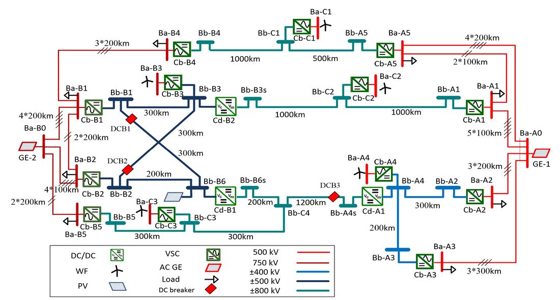
Figure 6 - BM6 - HVDC Grid Interconnecting two AC power systems
BM7 – Large comprehensive HVDC grid model
This model is comprised of BM1, BM2, BM3 and BM4 interconnected. BM7 is designed as a large comprehensive DC grid with more than 20 terminals, multiple DC voltage levels interconnected by DC/DC converters, multiple energy resources, to cover most different applications of DC grids and to meet the needs of most different research purposes. Due to its large size and complexity, it is not suitable for EMT studies which model all components. Some studies may wish to use detailed EMT representation for parts of the model, and simplified models for other sections – this was partly behind the thinking of forming this model from smaller sub-systems. It can be used for RMS dynamic studies, with part of the system modelled in detail; hybrid electromagnetic and electromechanical transient studies, with part of the system modelled in detail; DC grid planning studies; design and verification of power flow controllers; design and verification of DC grid system coordination control functions.
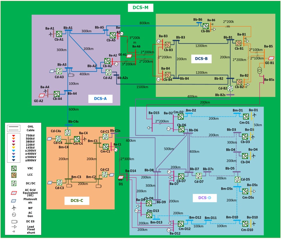
Figure 7 - BM7 - Comprehensive HVDC grid
Modelling and verification of the benchmark models
The load flow and EMT models of the seven benchmark models were built with common used offline and RT simulation software packages/platforms named Matlab, PSCAD, EMTP, DigSilent, RTDS and Opal-RT Hypersim. The power components of the models are built based on previous Cigre brochures or on the most standard/general model available in the literature and the corresponding software packages. These are briefly described in the Technical Brochure, with references to literature providing more detailed coverage. They include AC/DC converters, DC/DC converters, DC circuits (both OHL and cables), renewable generation, and conventional AC equipment. It should be noted that some benchmark parameters are generic and will need adjusting for specific studies. In particular this Technical Brochure makes no recommendations on protection strategies.
In total, there are seven (7) model file folders containing 38 model files (i.e. 9 LF models under normal operating conditions, 9 load flow models under (N-1) operating conditions, 10 EMT offline models and 10 real time simulation models), and one (1) file folder containing one excel spreadsheet file for (N-1) remedial action schemes and the complete (N-1) study results. The descriptions, software and sample results to allow users to undertake research and development in a common framework are provided in the Technical Brochure. This should aid innovation in this increasingly important field.
The specific model files attached to the Technical Brochure are:
- Load flow models under normal conditions for all models, in Matlab;
- Load flow modes under N-1 contingency conditions for all models, in DigSilent PowerFactory;
- EMT simulation models in PSCAD for BMs 1 to 5;
- EMT simulation models in DigSilent PowerFactory for BM 6;
- EMT simulation model in EMTP for BMs 4 and 7;
- EMT real-time simulation models for the RTDS platform for BMs 1 to 4;
- EMT real-time simulation models for the Opal-RT platform (Hypersim) for BMs 1 to 5 and 7.
Conclusions
The Technical Brochure has been prepared to help the engineering community study the important emerging field of multi-terminal and grid systems utilizing HVDC. It provides a wide-ranging study of HVDC systems around the world, and literature on multi-terminal and grid systems. It summaries the present system models for HVDC systems and grids. It develops seven benchmark models, with justification for their choice and summaries the key results, as well as online models across a variety of off-line simulation and real-time simulation platforms. It will provide a substantial resource to help users, researchers and developers of HVDC systems across a variety of study areas.

Other Technical Brochures