Dynamic loading effects on overhead lines: impact on structures
The Technical Brochure provides an overview of dynamic analysis and its impact on transmission lines supports. Techniques for dynamic analyses to obtain line response under time-dependent loads are presented. The brochure discusses dynamic load events and transmission line performance. Examples demonstrate the use of dynamic analysis in predicting the dynamic response of line sections. The advantage of dynamic analysis is emphasized considering the perspective of the standard practice of transmission line structural design.
Convenor, Author
(US)
L. KEMPNER JR
Secretary, Author
(CA)
A. HALDAR
F. ALMINHANA (BR), R.C. RAMOS MENEZES (BR), J.B.G.F. DA SILVA (BR), D. RICO (ES), D. BIEDRZYCKA-PIEGAT (PL), F. LEGERON (CA), G. GHEORGHITA (RO), J.T.F.M. GAIVÃO (PT), P. MARAIS (US), M.S. ERMOSHINA (RU), V. NUMMINEN (FI), T. OKAMURA (JP)
Corresponding Members: C. LAUB (CZ), D HUGHES (NZ), C-H. PARK (KR), K. S. HUN (KR), E. THORSTEINS (IS), M. RAVENA (CL), H. HAWES (AU), N. RIBEIRO (PT), N. LEMIEUX (CA), R. LAKE (AU), P. CHAPMAN (NZ), S. LANGLOIS (CA), R.P. GUIMARAES (BR), T. KAMIBAYASHI (JP), X. H. ZHANG (CA)
Reviewers: GHYSLAINE McCLURE (CA) and ASIF BHANGOR (AU)
Despite time dependent loads being treated in a quasi-static fashion, most of transmission line loads vary over a period of time, as illustrated in figure 1. Transmission lines are structural systems that extend over a significant distance and are exposed to a variety of meteorological, topographical, and geographical conditions. Examples of dynamic loads are wind, and wind-and-ice storms, as well as earthquakes. In addition to these events, there are other types of dynamic loads caused by conductor breakage and insulator string failure that can also impact the performance of transmission lines.
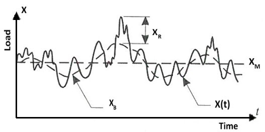
Figure 1 - A Typical Time History of Load (Wave Form)
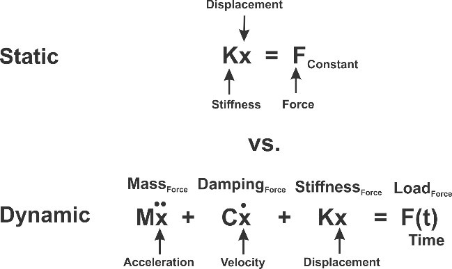
Dynamic analysis requires several parameters to be defined in addition to the static structural stiffness. These parameters include component masses, damping properties, and the time dependent dynamic loads. A simple comparison of these parameters for a typical linear system is shown in the following two equilibrium equations for static and dynamic analyses.
Ideally, the responses of all transmission line systems should be obtained based on time dependent loads and dynamic analysis, since this represents the real-world situation. This concept is not practical in an office environment in most of the situations, and therefore, simplified approaches based on equivalent static loads are used in line design. However, there are special cases when the designer should consider a dynamic analysis, such as for large river-crossings, special long span configurations, or for new non-traditional tower designs. Additionally, dynamic analysis can be a useful tool for tower failure investigations to determine the ultimate limit states of towers, and to develop the load magnitudes for simplified static analysis methods.
The transmission tower is part of a system consisting of multiple towers connected by multiple wire systems. These structural components have unique dynamic characteristics and can be subjected to different time varying load magnitudes. The ability to perform advanced dynamic analysis has been improving continuously over the past decades as numerical methods and computer capabilities are developed. Figure 2 depicts a flow diagram illustrating the solution types employed in a typical dynamic analysis. The two basic approaches that are considered in a dynamic analysis are linear and non-linear. The non-linear analysis can address large displacement as well inelastic material behavours.

Figure 2 - Dynamic Analysis Methods
Practically all structural loads applied to transmission line systems can be considered dynamic. This can be either in the initial state, such as wind, or sometime during the service life caused by ice drop-off, broken wires, or failed insulators. The main events generating significant time-dependent loads on transmission lines are presented here. Since wind is the most common source of dynamic loading on line components, the dynamic loads impacting transmission lines can be grouped into either wind-induced or wind-independent loads. The structural design of transmission line components is to a major extent governed by wind loads in most parts of the world not affected by atmospheric icing. These loads are time dependent, even though they are assumed as static loads, and their magnitudes vary vertically on towers and wires as well horizontally along the wire spans (Figure 3).
Figure 4 illustrates time varying member stresses for the main legs of a tower responding to a wind load event. Traditional transmission line design standards adopt simplified static (quasi-static) wind models based on synoptic boundary layer winds originated by extended pressure systems (EPS), i.e. extratropical cyclones. EPS events are responsible for the strongest gust winds in many parts of the world. The performance of transmission towers designed to the appropriate extreme wind speed has typically been acceptable. It should be noted that although these models are widely used, and experience has proved that they produce adequate results in many situations. However, they cannot adequately either represent all wind events or capture the full impact on structures.
Most tower failures can be attributed to narrow high wind gusts exceeding the design wind velocity. A narrow high wind gust can affect a single tower, or both the structure and its connecting transmission line spans simultaneously. The application of a narrow high wind gust is further complicated by a lack of understanding of the characteristics of localized high intensity winds caused by downbursts, also referred as thunderstorm winds.
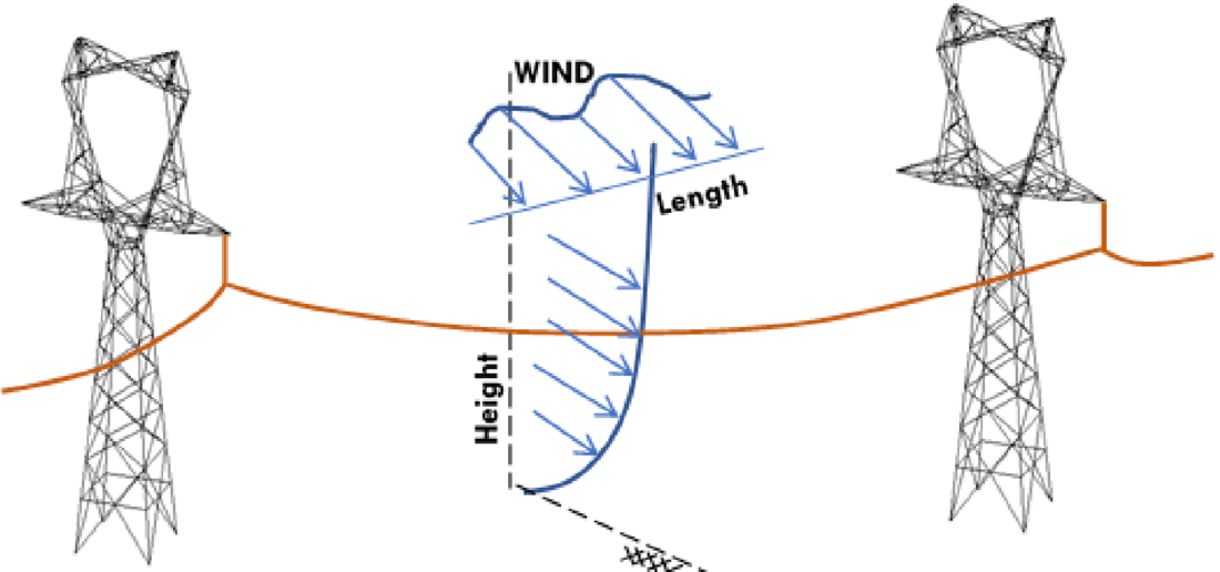
Figure 3 - Wind Loads on Transmission Lines
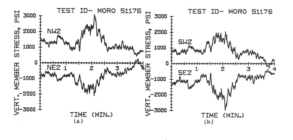
Figure 4 - Transmission Tower Main Leg Stress - Wind Load Response
In a transmission line system, there can be structures and structural components that may be sensitive to dynamic wind loads and in this case a full dynamic analysis should be considerd. Examples are large river-crossings and towers with unique configurations. The application of wind loads to very long spans, with or without tall transmission towers should be carefully reviewed to consider any potential effect due to the dynamic response of the conductor system, or dynamic interaction with the “support system” of tall towers. Tower (tubular and lattice) members can also be subjected to wind induced vortex shedding vibration. In exceptional situations, fatigue damage has been observed at the tower member connections.
The wire spans can also be subjected to time varying loads and this can cause the wires to vibrate dynamically. Aeolian vibration is a high frequency low amplitude motion of the wire that can cause conductor fatigue, which is likely to develop at the conductor attachment points at the clamp mouth (conductor “take off” point). This type of vibration can also cause tower members to develop fatigue cracks and loosen connection bolts if the system is not damped appropriately. Conductor galloping, unlike aeolian vibration, is a low frequency high amplitude, primarily a vertical motion induced by a moderately strong steady wind on an asymmetrical ice shaped conductor. The conductor movement during galloping can result in infringement of operating clearances between wire phases, failure in insulator assemblies and fittings, as well damage to structural framing members. Wind induced vibration on conductor bundles can cause vibration problems that differ from those encountered in a single conductor. In addition to galloping and aeolian vibrations, conductor bundles are also affected by low-frequency “sub-span oscillations” induced by wake effects between the sub-conductors, and this can lead to conductor damage at spacer damper locations.
Apart from the dynamic wind-induced loads, there are other dynamic loads that are wind-independent loads, which can impact significantly line components and should be considered in line design. These loads are: ice and snow shedding; conductor and shield wire breakages; insulator failures and earthquakes.
Ice and snow loading events are typically classified as static loads. But after the ice/snow storm, this loading can become dynamic when the ice/snow sheds from wires in the full spans or segmented sections of the spans due to change in temperature. This loading event is called “sleet jump” or “snow jump”. Ice/snow shedding causes two effects, potentially large wire movements and impact loads. An ice shedding event can cause unbalanced bending and torsional loads on a tower that should be considered under these situations.
Conductor breakage can induce large unbalanced impact loads on transmission towers and is regarded as the most frequent triggering event of severe longitudinal cascades, progressive failure of the line structures, figure 5. Conductor breakage produces shock waves that propagate throughout the line system (typically a line section defined between two dead end structures).
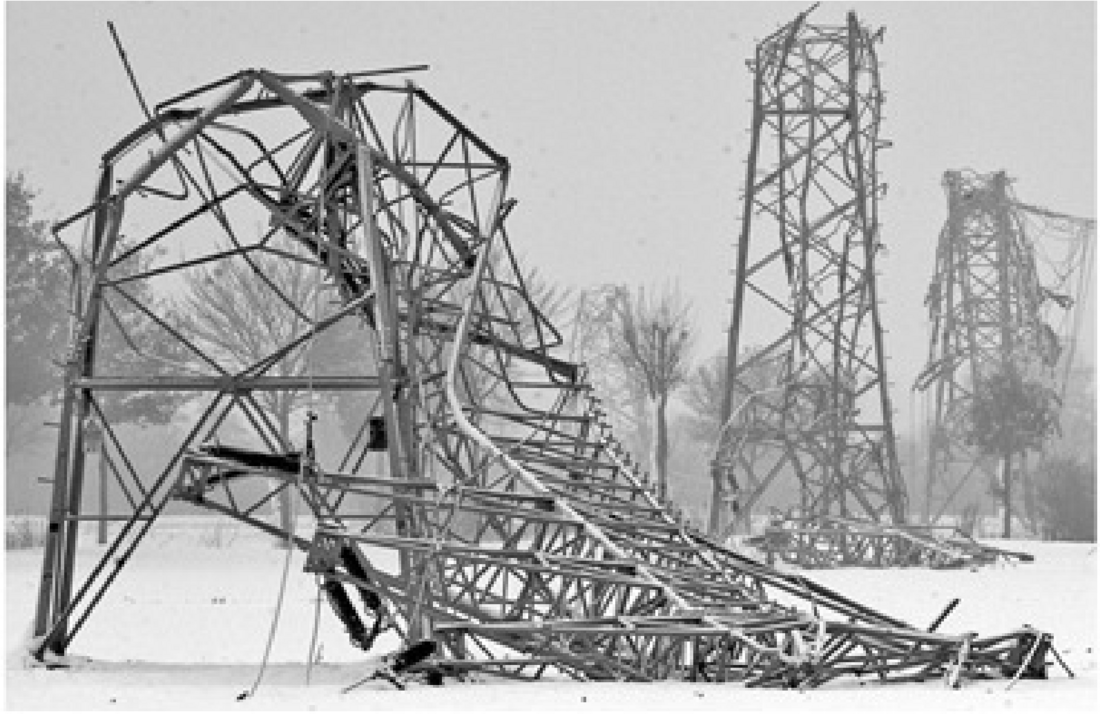
Figure 5 - Transmission Line in Germany Affected by Longitudinal Cascade (source: Starossek, U.; 2009)
In the past decades, several systems and strategies have been developed and implemented by electrical utilities across the globe in alleviating line collapses, although some of them have shown to have limited success. One cascading mitigation strategy is called failure containment design philosophy. This strategy is based on the determination of design longitudinal impact load factors and placement of towers within a line considering an acceptable number of cascading tower failures in the line section. Other cascade mitigation devices such as load control sliding clamps and load-limiting systems protect the supports from excessive loads by providing additional slack and localized dissipation of energy.
With respect to seismic performance of transmission line systems to earthquakes, a full dynamic analysis is the only mean to investigate the response of transmission line systems (towers, conductors and foundation-soil interaction) to earthquake events. However, earthquake analysis is typically not applied to transmission line design. Historically, transmission line systems performed adequately to inertia loading during significant seismic events. Line support collapses have occurred, but these typically have been related to failures of the foundations from liquefaction, lateral spreading, or earthquake generated landslides. Another earthquake related failure mode of transmission line towers is earthquake generated rock falls. Although previous observations may apply to transmission line structures under usual conditions, it is recommended to carefully consider earthquake events for special and/or unique transmission line structures, such as large span crossings and/or very tall and slender towers installed in zones of high seismic activity.
It is important to have a basic understanding of the parameters and modelling assumptions used in a dynamic analysis. The appropriate mass, damping, and stiffness of the structural model are critical to obtaining realistic dynamic response results.
The effects of dynamic loading rate on line component capacity is also a very important issue. Rapid loading can arise from broken conductor loads, ice shedding, etc., and the question that needs to be addressed is how a line component (e.g. tower members, insulator assemblies and foundations) responds to a rapid load event. Several structural systems and components have been tested to determine the effects of dynamic loading rate on failure modes. The behaviour of tower foundation capacity under rapid dynamic loads has also been investigated through full broken conductor tests on transmission lines (CIGRE TB 788).
There is a significant number of published literatures where advanced structural dynamic analysis has been used to better understand the performance of transmission line systems. These investigations provide examples on how to carry out and apply dynamic analysis on overhead lines, and benchmark analysis in some cases. They have shown that numerical methods can be extremely powerful, i.e. they can produce highly accurate results when built upon a solid theoretical formulation and are properly calibrated using experimental tests.
It is important to keep in mind that the equivalent static loads, usually provided in design codes, are derived to provide a similar component response as it would be subjected to a real dynamic loading. Hence, these given equivalent static loads are valid within a range of applications that satisfy the premises from where they were derived. The boundary between the range where they are valid and where they are inaccurate depends on the structural configuration and type of loading, and may be imperceptible by the industry and/or by transmission line engineers, who may not be familiar with advanced structural analysis concepts. In this context, structural dynamic analysis capabilities are an important tool to understand the structural performance of transmission line components when subjected to time-dependent loads. Structural dynamic analysis demands non-trivial efforts in modelling loads, member resistance, and structural response.
To review the existing literature, as well as to collect the available information on the current industry practices around the world on this issue, a Working Group was created by CIGRE (WG B2.24), aiming to consolidate information in an unique document that could be a reference on this subject for transmission line engineers.
Working Group members consider that the transmission line design industry will benefit as investigations and research continue to demonstrate the application of advance dynamic analysis tools to better understand tower/line system performance. The current studies clearly showed that a balance should be sought between impact of transient loading effects (short duration load with rapid rate of increase) on structural components and the increase in structural capacity. In conclusion, under the philosophy of the Load and Resistance Factor Design (LRFD) methodology, the dynamic characteristic should be simultaneously considered in both sides of the design equation by using adequate coefficients to achieve a consistent design practice. Results of full-scale tests, researched by the WG on several components, strongly support this finding
In this context, a CIGRE Technical Brochure is being issued addressing above mentioned themes and providing a comprehensive overview of dynamic phenomena impacting transmission line supports and dynamic analysis techniques employed to obtain line response under time-dependent loads. The fundamental concepts of dynamic analysis and modelling are examined. Relevant dynamic events inducing time-domain dynamic loads acting on transmission line components, especially line supports, are examined. A brief review of relevant published research employing advanced structural dynamic analysis techniques is provided to depict the importance of the dynamic performance of transmission line problems. Examples employing time domain dynamic analysis in predicting the response of typical line sections to dynamic loads are also provided. These examples illustrate the usage of advanced dynamic analysis to transmission line applications. Solution procedures employed to solve the equations of motion in each example are discussed. The most significant modelling considerations e.g. element types, dynamic loading input generation, and boundary conditions are indicated as well the main analysis parameters adopted, such as time step of integration and damping values. The necessity of dynamic analysis is discussed under the perspective of the standard practice of transmission line structural design.

Other Technical Brochures