Atmospheric and altitude correction factors for air gaps and clean insulators
The influence of atmospheric conditions on the dielectric strength of external insulation is complex. This is because the degree of influence is different for different discharge processes, e.g., corona, streamer, and leader discharges. At the same time, the type of discharge processes that may appear across the insulation is determined by many other parameters.
Members
Convenor
(DE)
J. RICKMANN
Secretary
(CN)
J. FAN
L. AREVALO (SE), R. DIAZ (AR), D. DE MELLO (BR), D. YUJIAN (CN), A.-P. ELG (SE), E. KYNAST (DE), Q. LI (CN), Y. LI (AU), Y. LIAO (CN), R. MAREK (US), C. NYAMUPANGEDENGU (ZA), S. OKABE (JP), N. PARUS (YA), A. PIGINI (IT), D. TABAKOVIC (US), D. WU (SE)
Corresponding Members
A. BOSMA (SE), J.C. MARTINEZ MAGDALENO (MX), M. RAMIREZ (MX), G. RIZZI (IT)
Those related parameters may be grouped into three categories (Figure 1):
- Ambient conditions: temperature, pressure, humidity, rain, snow, and pollution.
- Applied voltage (waveforms of the applied voltage): LI, SI, AC, DC, and other possible waveforms.
- Insulation configuration (insulation characteristics): electrode shape, gap size and arrangement, gap complexity, etc..
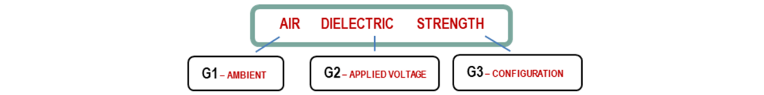
Figure 1 - Influencing factors for air dielectric strength
Medium and High voltage equipment (i.e. circuit breakers, disconnectors, arresters, bushings, insulators, instrument transformers, etc.) requires reliable criteria for development and designing to ensure long-lasting endurance in service.
To achieve these objectives, dielectric tests (Type, Sample and Routine Tests) are performed in HV Laboratories, which may be located at various altitudes. Additionally, the equipment itself is normally required to be installed and to be fully functional at various altitudes and in different environmental conditions.
Different standards and guidelines for insulation coordination and testing are available. However, several different approaches to atmospheric and altitude correction exist in these documents, resulting in confusion and ambiguities. Therefore, clarification and new recommendations are needed.
In the case of applying atmospheric correction factors in testing, two different correction procedures are applied:
- Correction of the disruptive discharge voltage at given atmospheric conditions to the voltage which would have been obtained at the standard reference atmosphere.
- Correction of a specified voltage to a test voltage in a laboratory with its actual atmospheric conditions at the time of test (converse method)
In the case of insulation coordination and in the design stage of the apparatus, not all parameters of atmospheric conditions in service and not all geometries or insulation configurations are normally available. This means simplifications are necessary which lead to in practice an altitude correction only approach, which has the following implications:
- A correction for the withstand voltage is calculated for higher altitudes referring to the withstand voltage at sea level to fulfil the dielectric requirements.
- The simplified model needs to cover for the missing parameters, i.e., temperature and humidity, to avoid breakdown, which in many cases has proven to be insufficient.
Scope
The scope of the Working Group was:
- Check and evaluate the existing correction factors (temperature, pressure, absolute humidity) for AC, SI, LI and DC test voltages in voltage systems greater 1000 V relevant for installation up to 6000 m above sea level, for air gaps and clean insulators.
- Collect available new test results and initiate round-robin-tests, if necessary.
- Give guidance on modifications of the atmospheric and altitude corrections, when necessary.
Structure of the TB
The Technical Brochure summarizes the work carried out by the Working Group with experts from utilities, OEMs, academia, consultants, R&D organizations and industry experts on Insulation Coordination and HV Engineering and technologies. The experts of WG D1.50 have put their experience and knowledge together to create this brochure between 2012 and 2022.
The Technical Brochure addresses the subject topic relevant to all stakeholders of T&D equipment and technology, which included all those involved in the selection, specification, design, manufacture, and exploitation management of MV and HV equipment. The document focuses on the implementation of Atmospheric and Altitude Correction Factors (AACF) for air gaps and clean insulators that are typically used for overhead lines and in HV substations and equipment.
The Technical Brochure further provides an overview of the existing AAFC methodologies, stipulated in various IEC standards. It also presents the current and expected future trends to be included in the revision of standards and procedures, pointing to the need for further research, testing and standardization. It features eight main chapters and 6 appendices.
The first chapter (Chapter 1 "Introduction") presents the goals and motivations as well as details of the work. The terms atmospheric correction and altitude correction are often used in parallel and interchangeably. The chapter aims to show the common ideas and the differences between these two terms. It presents the application principles of atmospheric correction in dielectric testing and insulation coordination, and explains the differences between atmospheric correction and altitude correction.
Chapter 2 “Physical Background of atmospheric corrections on air discharge”, provides an overview of the discharging mechanism in the air. Then it explains the streamer and leader behaviors in short and long gaps. This section finishes with a discussion of the influences of air density and humidity and their impact on air discharges.
Chapter 3 “Historical Background of existing correction methods and their deficiencies” provides a historical overview and background of the existing correction methodologies, including their deficiencies and inadequacies. It covers atmospheric correction for testing as given in IEC 60060 (published in 1973, 1989 and 2010) as well as for insulation coordination (IEC 60071).
Chapter 4 “Comparison of existing correction methods in different standards and historical test results” is dedicated to the analysis of the accuracy of existing correction methods in different standards (IEC and IEEE) when compared to published test results. The comparison of the results against the sparse test data on which the methods are based, show the need for further research.
The analysis of the historical test data for switching impulse in Chapter 4, on which the current correction methods are based, must be seen with some caution since the amount of data is fairly limited. It can be seen though, that the methods in IEC 60-1 [S-1], IEC 60060-1 [S-3] and IEC 60071-2 [S-5] agree well with each other and are more conservative for impulses with standard front times, whereas yield too low corrections for shorter to critical front times.
Chapter 5 “Correction methods for long gaps (air density) – Breakdown tests and altitude correction” gives an in-depth examination of correction methods used for long gaps (air density). It reports recent results of tests on long air gaps at high altitudes up to 4200 m for AC,DC, LI and SI and discusses these new results in relation to the current correction methods (Figure 2).
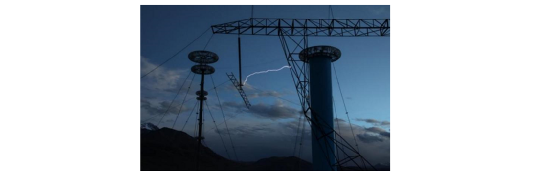
Figure 2 - Conductor window test set-up at 4200 m
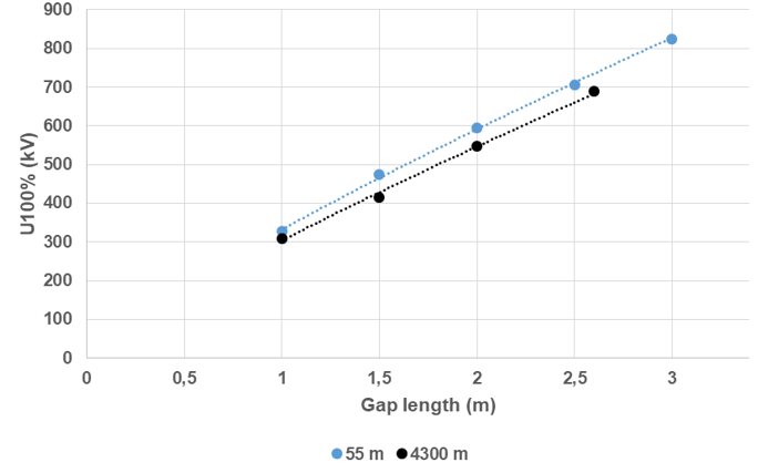
Figure 3 - Rod-plane AC test data corrected to standard atmospheric conditions
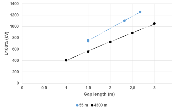
Figure 4 - Rod-plane DC test data corrected to standard atmospheric conditions
Figures 3 and 4 show AC and DC test data corrected to standard atmospheric conditions for rod-plane configurations from 1 to 3 m indicating the necessity of a correction factor for high altitudes, after the application of the standardized atmospheric correction factors.
Chapter 6 “Correction methods for short gaps (air density)” provides different information on existing Correction methods for short gaps. The chapter briefly illustrates the physics of breakdown in short gaps, and gives guidance for correction as a function of gap size and characteristics, while exposed to different kind of voltages.
In the past it was believed that short gaps, < 1 m, do not need any humidity correction when it comes to the apparatuses installed at elevated sites (1000 m.a.s.l. and above) or in different atmospheric conditions. However, recent work, as presented in Chapter 6, shows that the humidity influences are more pronounced in short gaps where the breakdown level exceeds 500 kV/m, typically needed for streamer propagation. The available data show discrepancies in the correction method of IEC 60060-1, especially related to humidity corrections which are not defined for short gaps in the standards. The IEC standard does not make specific mention for short gaps, but it is true that the g parameter criteria is not more applicable to short gaps, because the average positive streamer propagation gradient is greater than 500 kV/m
Chapter 7 “Humidity correction” outlines the current standardization efforts concerning absolute humidity corrections, and highlights further standardization needs in this area. Humidity corrections are strongly intertwined with the air density corrections in the present standards.
In dielectric breakdown, there are principal differences between short and long air gaps. The humidity correction is divided into short gaps (≤ 1 m with streamer predominant breakdown), intermediate gaps (1 m < d ≤ 2 m) and long gaps (d > 2 m with leader predominant breakdown). The focus is on long gaps which are predominant for power transmission lines at high altitudes. The aim is to provide an update of the present IEC 60060-1 correction approach limited to 2000 m.a.s.l. to encompass high altitudes.
A background is given on how the breakdown mechanisms are affected by the humidity. For long gaps, important factors are:
- voltage stress type, i.e., DC, AC, SI and LI,
- shape of pre-discharges,
- number of consecutive impulses for SI, time interval between impulses for LI, and ion build-up close to surfaces, are analysed.
Chapter 8 provides conclusions stemming from the work presented, whereby the current status of research and application of atmospheric and altitude corrections is summarized and future necessary research work pointed out.
The Technical Brochure ends with the following Appendices:
Appendix B “References”, is a list of the literature that was used to prepare the Technical Brochure. It comprises around 140 publications (standards and papers) and might be helpful to people who need more comprehensive information on this particular engineering topic.
Appendix C offers a Draft Proposal of the German National Committee for a new Annex to IEC 60071-2, 3rd Ed.
Appendix D provides all tabulated data used for correction curves in Section 4.2 of the TB.
Appendix E presents all currently available test data, including those used to formulate the current correction methods.
Appendix F provides an example of the application of atmospheric correction factors in disruptive tests.
Finally, WG D1.50 strongly believes that further tests and research are necessary to improve the present Standards.
The Working Group wants to thank the China Electric Power Research Institute, Eskom and University of Witwatersrand for providing the new data for high altitudes as well as for AC and DC breakdown in different gaps.
The Working Group wants to thank also the Correspondings Members J. C. Martinez Magdaleno, M. Ramirez and G. Rizzi for their help to retrieve the original tests data used to formulate the current correction methods.

Other Technical Brochures