The First MVDC Station Project in Korea
A portion of future renewable generation will be linked to distribution grids and distribution systems should be re-organized to meet end-user’s required energy demand. When renewable energies are integrated into AC networks, there is an increased risk of instability. One solution is to increase the DC grid connection capacity.

Background
Future distribution power systems will supply nearby industrial areas with the required energy through the decentralized power generation and by controlling active power. To this end, the development of MV (Medium Voltage) DC technology and its implementation are necessary to effectively control two-way power flow rather than passive one-way flow in the distribution grid. Such efforts enable us to maximize the capacity and optimize operation by avoiding accidently delayed connections of renewable generation into the distribution grid.
A pilot project has been launched in Korea’s Jeon-Nam province, a region with a large amount of renewable energy already in operation (4.5 GW in 2021), and therefore very appropriate to evaluate this pilot project. Renewable energy in this province is projected to expand to 20.6 GW by 2030, bringing the total portion of renewable energy to 35% of Korea’s total renewable energy capacity (58.8 GW) planned for 2030. Unfortunately, the existing line in Korea has been only designed to optimize the load current supply without such a rapid expansion of renewables. It is likely that such expansion would cause not only distribution line overload but also delays for the connection of renewable energy into the grid. To solve the upcoming and anticipated technical issue, the plan is to transmit more power through the existing distribution line by adopting MVDC, replacing the current AC 22.9 kV while meeting the required condition related to grid stability.
Business Model Using MVDC Technology
Over the past decades, electric power industries have been primarily serving AC power systems. Newer trends have shifted to greater demands serving DC power systems of semiconductor-based customer facilities. MVDC technology could give the right solution to the electric power infrastructure without AC/DC conversion considering the wide spread of electric vehicle (EV) charging, energy storage systems (ESS), Data Centers, and more. For example, an investigation on Data Centers directly connected to MVDC system has reported to be 20% more efficient compared with AC connected conventional systems.
Current regulation in Korea limits the maximum connecting power to 20MW when the renewable generation is linked to the existing AC distribution grid, making it exceedingly difficult to connect renewable energy over 100 MW or higher. The application of MVDC technology solves this issue by minimizing the number of distribution power lines required for transmitting the higher power capacity. In addition, the distribution power system reliability will be improved by isolating any potential faults and two-way power flow efficiency will be improved. Potential economic advantages over the conventional AC system will also be expected.
Design of MVDC Station
In Korea, KEPCO has launched an innovative project to install the first MVDC station at ±35kV which will be placed into commercial service for 30 MW of PV (photo-voltaic – solar) in 2023. The aims are to increase transmission line power capacity from AC 20 MW to DC 30 MW and to modify the regulation of insulation distance from AC 20m to DC 6m~7m; the consequent change in circuit configuration could permit KEPCO to triple the current power supply in the distribution system. By building such a novel system, relevant technologies and tools evaluating technical advantages have been achieved in many aspects including operational sequence in steady state, and the ripple effects from any malfunctions or transient states.
Based on PTP (point-to-point), this MVDC system consists of a rectifier and inverter station (as shown in Fig.1). They are composed of a converter valve, C&P (control & protection) system for converter, coupling transformer, and cooling system. There are six arms at the inverter and rectifier station respectively, where each arm consists of 30 submodules including 2 redundancies, based on the half-bridge MMC (modular multilevel converter) topology.
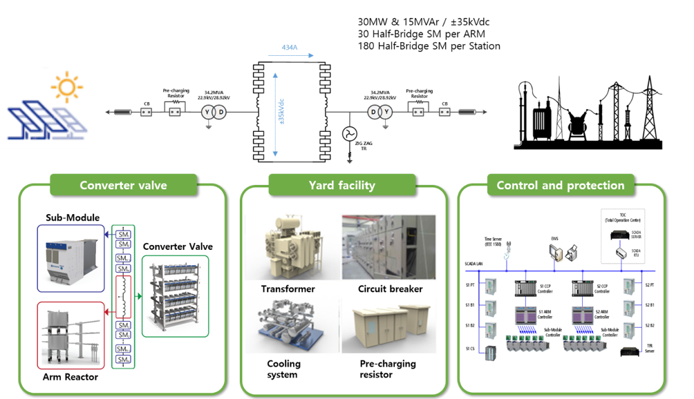
Figure 1 - Overall System Diagram of MVDC Station
Regarding the converter valve system, it has two main parts. One includes unit valves with serial submodules consisting of capacitors and semiconductor switching devices for regulating output voltage. Redundancy is included to facilitate normal operation with the occasional occurrence of malfunctions. The other is the reactor at each arm, should a DC short circuit occurs, to limit short circuit current. In this way, the circulating current inside the converter could be reduced to less than 20 A and the protection of the switching semiconductor elements could be safely provided. The main specifications of the MVDC Station are summarized in Table 1.
| Item | Technical Value |
|---|---|
Rated Power | 30 MW |
Rated DC Link Voltage | ±35 kV |
Rated DC Link Current | 434 A |
Number of sub-modules | 180 pieces |
Rated Voltage of sub-modules | 2.5 kV |
Arm reactor Inductance | 18 mH |
To verify the reliable controller function, tests have been carried out in the HILS (hardware in the loop simulation) system: start/stop sequence test, steady-state control test, transient-state control test, and protection response test. The response rate of the MVDC system providing active and reactive power can be investigated in various ways dependent on the Ramp-Rate setting. One of the steady-state control tests is the response speed measurement test showing that the maximum response rate is within 100 ms at 1 pu variation by simulation. The normal operation of the system with full 30 MW power is available, and the response time at PCC (point-of-common coupling) required by the utility is verified without disturbing the grid operation.
Figure 2 shows the voltage and current evolution at the system’s main components such as DC Link, converter arm, and PCC due to a DC short-circuit accident, i.e., the worst failure situation of MVDC converter system. It could be suggested that the fault duration time is 250 ms considering CB (circuit breaker) operation and BF (break failure) protection. Accordingly, this could be employed as the condition of a DC short-circuit test. The results also imply that the maximum instantaneous fault current is 4.08 kA, and 3 kA could be allowed to flow continuously until the fault is cleared. In this way, the converter is protected against any potential DC short circuit as the apparatus is designed to withstand fault currents.
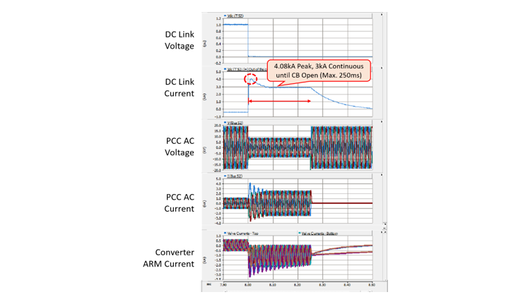
Figure 2 - Short circuit fault in DC link by simulation
Conclusion
A novel MVDC technology is likely to meet the growing demand more efficiently for large-scale power loads required for EV charging stations, ESS, and Data Centers. For this purpose, several core issues should be solved such as increasing the connection capacity, improving connection delays of renewable energy, and controlling power flow. In near future, DC railway and electrical ships will be tested through a pilot project of an AC/DC hybrid distribution network. Hyosung hopes to contribute to the DC distribution business and establish relevant regulations throughout the reliable operation experiences obtained from Korea's first MVDC pilot project.
Acknowledgement
The author would like to express his sincere gratitude for the thoughtful advice of Emeritus Prof. J.Y. KOO in making the manuscript under the technical cooperation with 5 engineers working at Hyosung heavy industries corporation. They are: H.S. PARK, H.H.YOO, J.C.LEE. D.S.LEE, J.B.KIM.
References
- KIEE Magazine, Trend of MVDC Technology
- CIGRE Technical Brochure 793 Medium voltage direct current (MVDC) grid feasibility study
- NEDO, Current Status of DC Distribution System by KEPCO
About the author

MINSOO LEE was born on the 1st July 1984 in Korea. He received the Bachelor degree from Korea University in 2008 in Korea. Afterwards, he has been working at Hyosung heavy industries as a senior engineer to provide solutions in the area of AC & DC substation.
He has joined CIGRE as a working group member since 2017 and now appointed as the observer member of Study Committee B3 in 2022.
Thumbnail Credit: Photo by Denis Sebastian Tamas on Unsplash
Suggested content